In this post we implement a clock generator module for the audio codec on the ZedBoard. The Clock Generator is the second of the four major components in our ZedBoard Audio Processor design’s top level, as mentioned in a previous post.
Clocking the ADAU1761
The ZedBoard’s onboard ADAU1761 audio codec requires a clock signal to operate, which can be obtained by a) using an internal PLL in the codec itself, or b) providing a Master Clock signal generated by the Zynq. Our ZedBoard Audio Processor uses the latter.
When bypassing the PLL, the clock provided by the FPGA must be 256, 512, 768 or 1024 times the desired base sampling rate. We opt for a base sampling rate of 44.1 kHz and the highest multiplying factor, which results in a Master Clock frequency of 45.158 MHz. Using a lower Master Clock frequency would result in a reduced amount processing cycles available in the audio codec’s built-in DSP engine. This isn’t relevant for our design, but good to keep in mind anyway.
Clock Generator Module
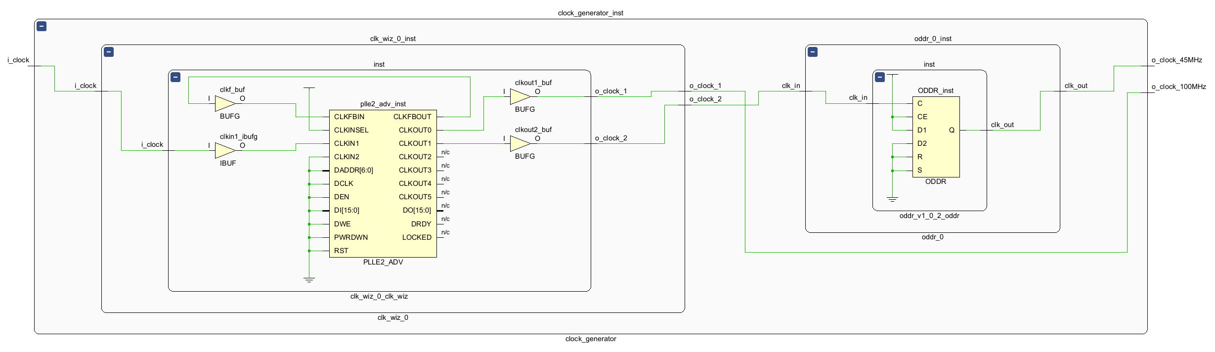
The Clock Generator module for the audio codec’s Master Clock includes two Xilinx IP cores: a Clock Wizard and an ODDR. This is shown in the figure below.
Clock Wizard
The Clock Wizard core receives the 100 MHz clock signal from the on-board oscillator and derives the Master Clock signal from it. The multiplier in the Clock Wizard is not able to generate the exact frequency required by the audio codec (45.158.400 Hz), so we’ll take the closest frequency it does generate (45.161.290 Hz). This should be accurate enough for our application.
In addition to the Audio Codec Master Clock, the Clock Generator Module also produces a 100 MHz clock signal that will drive the logic in our design.
ODDR
Whenever we generate a clock signal in an FPGA to drive an external device, we shouldn’t simply assign an internal clock signal to an external FPGA pin. Instead, we should always use the Output Double Data Rate (ODDR) primitive that is usually available in the IO resources of the pin we are using to output the clock.
An ODDR primitive has one clock and two data inputs. With each edge of the clock, it transfers the value from the matching data input to the data output. By setting the inputs to opposite values, it is possible to generate a clock signal with the same frequency as the input clock. It is critical to set the right input values, otherwise the polarity of the output clock could be unintentionally inverted.
Since using an ODDR primitive to generate an output clock is such a common use case, Xilinx includes an IP Core exclusively for this purpose. It is still an ODDR primitive under the hood, but it is setup in such way that the user only needs to connect the input and output clocks, which adds a bit of convenience and removes one potential source of error. However, this comes at the expense of flexibility, because it would not be possible to deliberately invert the polarity of the generated clock. This is shown on the right side of the figure above.
In the next post we will describe the SPI logic used for configuring the audio codec on the ZedBoard.
Cheers,
Isaac
March 7th 2022: updated to reflect that the Clock Generator now produces a 100 MHz signal for driving the FPGA logic.
One response to “003 – ZedBoard Audio Codec Master Clock”
Why is it recommended to not simply assign an internal clock signal to an external FPGA pin?