In this post we will go over the implementation of an LED Meter for our ZedBoard Audio Processor.
When working with audio we are not limited to using our ears, visual feedback from our processing and analysis modules is also an important element in our interaction with audio processing tools. Today we will turn the LEDs on the ZedBoard into a real-time LED Meter.
LED Meter IO Ports
Let’s start be defining our top-level IO signals and instantiating our entity in the Audio Processor Core.
As we discussed in the previous post, all our modules for analyzing and processing the audio stream will be instantiated between the Deserializer, which is always the block that receives data from the audio codec, and the Serializer, which is always the block that sends the processed data to the audio codec. We also mentioned that most modules for processing and analyzing the audio must follow the same protocol, with a ‘valid‘ signal indicating the availability of new data at the inputs and outputs.
We also mentioned that some modules only need to support the audio transfer protocol at their input because they don’t generate any audio data. This is the case with the LED Meter, which receives audio data and outputs the driving signals for the on-board LEDs. A synthesizer works the other way around: it receives control signals and generates audio data. We’ll get into sound synthesis later.
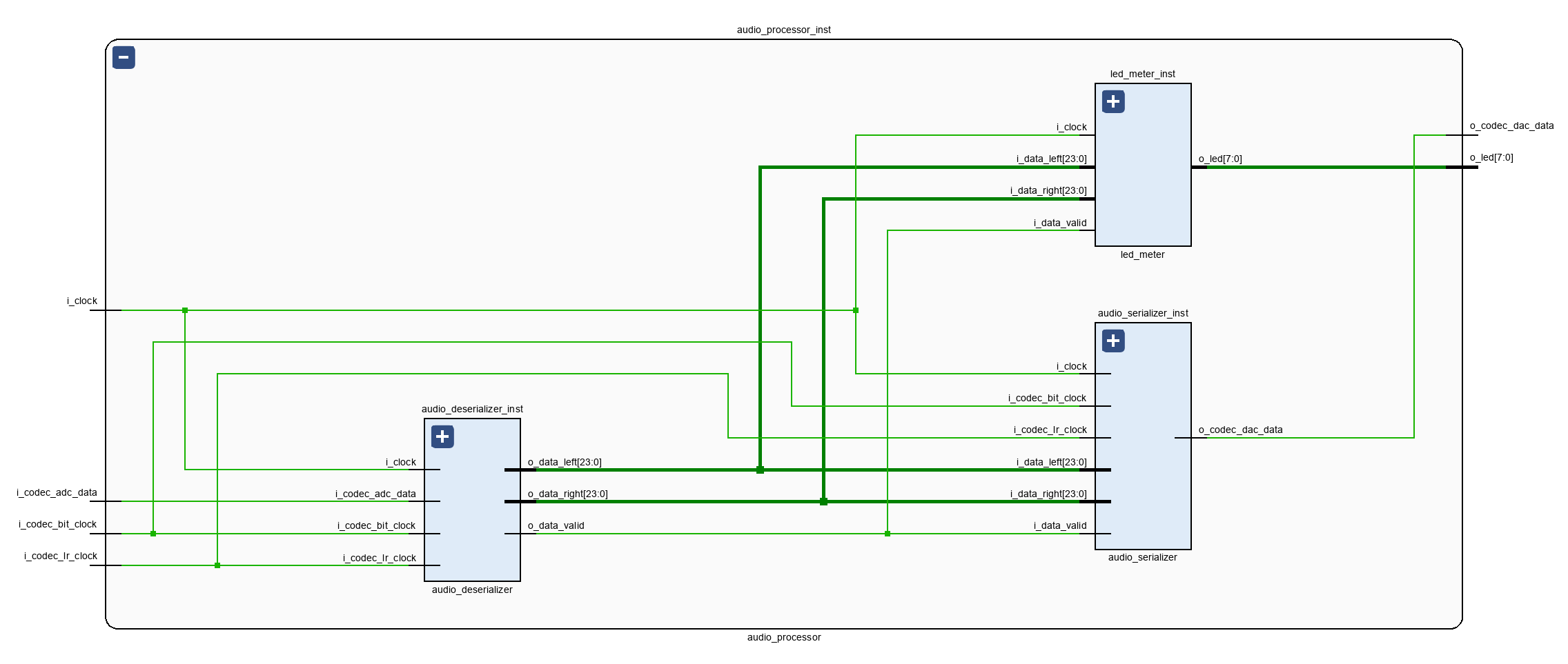
The figure below shows the LED Meter module instantiated within the Audio Processor Core. As it is our only module for audio analysis and processing so far, it receives the parallel audio data directly from the Deserializer.
LED Meter FSM
The LED Meter logic is implemented in a single FSM. It works as follows:
- Wait for the ‘i_valid_signal’ to be asserted and convert the stereo audio signal to mono
- Calculate the absolute value of the mono sum
- Update the LED display based on the absolute value of the mono sum.
Let’s look at each step in detail.
Converting the Stereo Signal to Mono
Because most modern music is produced in stereo, most LED meters will have two rows of LEDs, one for each channel. Since we only have a single row of LEDs on the ZedBoard, we’ll convert the signal to mono and generate a display with a higher resolution. It would also be possible to assign four LEDs to each channel, in which case we wouldn’t have to calculate the mono sum at all.
Converting a stereo signal to mono is pretty simple, we just have to add both channels together and divide the result by two. Now, we know that any division by a power of two can be implemented by shifting the data, but we also need to keep in mind that we are working with signed signals here, and the MSB represents the sign bit. So if we were to shift the data to right, we would need to make sure that the signals are declared as signed (or that we cast them as signed when performing the shift) or to perform a sign extension ourselves. Another option it is better to simply write ‘signal / 2‘ and let the synthesis tool take care of it (again, assuming that the signal is declared as or casted to signed).
Calculating the Absolute Value
As we mentioned earlier in the post, the LED Meter will be driven by the absolute values of our audio samples. We also know that the audio codec uses a two’s complement format to represent negative values. When extracting the absolute value of a two’s complement signal we need to first check whether the signal is non-negative, that is, the signal is either positive or zero. If that is the case, we don’t need to do anything else. If the signal is negative, we convert it to positive while retaining the same absolute value.
To find out whether a two’s complement signal is negative or not, we need to check the value of the MSB. If it is zero, the signal is positive. We are done! If the MSB is negative, we need to invert every bit in the signal and add one to the result. That will give us a positive number with the same absolute value as our negative number.
Updating the LEDs with Thermometer Code
In the last step, we need to turn our LEDs on and off based on the absolute value of our mono sum: the higher the value of the mono sum, the more LEDs should turn on. We do this by using the so-called thermometer code. In its basic form, thermometer code maps each binary value to a series of ones, which when stacked vertically resemble the way that a thermometer displays its temperature reading.
The thermometer code requires as many bits as non-zero values can be represented in the original binary code. Since we are dealing with 8+ million values, we’ll have to assign ranges to each LED, so that each one represents one section of the 0 to 8.388.608 range.
The complete code for our LED Meter is shown below.
module led_meter (
    input   logic i_clock,
    // Audio Input
    input   logic signed [23 : 0]  i_data_left,
    input   logic signed [23 : 0]  i_data_right,
    input   logic           i_data_valid,
    // LED Meter Output
    output  logic [7 : 0]   o_led
);

    timeunit 1ns;
    timeprecision 1ps;

    // Main FSM
    enum logic  [1 : 0]     {IDLE,
                            GET_MONO_SUM,
                            GET_ABSOLUTE_VALUE,
                            UPDATE_LED} main_fsm_state = IDLE;
    logic signed [24 : 0]   absolute_mono_sum;

    always_ff @(posedge i_clock) begin : main_fsm
        case (main_fsm_state)
            IDLE : begin
                absolute_mono_sum <= \'b0;
                main_fsm_state <= GET_MONO_SUM;
            end

            GET_MONO_SUM : begin
                if (i_data_valid == 1\'b1) begin
                    absolute_mono_sum <= (i_data_left + i_data_right) / 2;
                    main_fsm_state <= GET_ABSOLUTE_VALUE;
                end
            end

            GET_ABSOLUTE_VALUE : begin
                if (absolute_mono_sum[$left(absolute_mono_sum)] == 1\'b1) begin      // Negative value, need to convert to positive
                    absolute_mono_sum <= (~absolute_mono_sum) + 1;
                end
                main_fsm_state <= UPDATE_LED;
            end

            UPDATE_LED : begin
                // Convert to thermometer code to drive the LEDs
                if (absolute_mono_sum > 4194304)
                    o_led <= 8\'b11111111;
                else if (absolute_mono_sum > 2097152)
                    o_led <= 8\'b01111111;
                else if (absolute_mono_sum > 1048576)
                    o_led <= 8\'b00111111;
                else if (absolute_mono_sum > 524288)
                    o_led <= 8\'b00011111;
                else if (absolute_mono_sum > 262144)
                    o_led <= 8\'b00001111;
                else if (absolute_mono_sum > 131072)
                    o_led <= 8\'b00000111;
                else if (absolute_mono_sum > 65536)
                    o_led <= 8\'b00000011;
                else if (absolute_mono_sum > 16384)
                    o_led <= 8\'b0000001;
                else begin
                    o_led <= 8\'b0000000;
                end
                main_fsm_state <= IDLE;
            end

            default : begin
                main_fsm_state <= IDLE;
            end
        endcase
    end

endmodule
Now we have some real-time visual feedback for our audio data stream. Pretty cool, huh? And even cooler, this is the first time we get to do something meaningful with the actual audio data. In that spirit, in the next post we’ll implement a monitor controller, which will give us the chance to perform some basic operations on our audio stream, where we can actually hear the results. See you then!
Cheers,
Isaac