In this post we will go over the implementation of a SystemVerilog monitor controller for our ZedBoard Audio Processor.
In the previous post we implemented an LED Meter that shows the amplitude of our audio signal in real time. The LED Meter is a fantastic way to do some simple calculations based on the audio data and get visual feedback but, we obviously would like to make some simple changes we can hear. A Monitor Controller will be great for that.
What is a Monitor Controller?
In the professional audio world, the word ‘monitor’ is used to refer to the loudspeakers through which the audio is listened to, or ‘monitored’. A monitor controller is a piece of equipment that processes the audio signals going to the monitors.
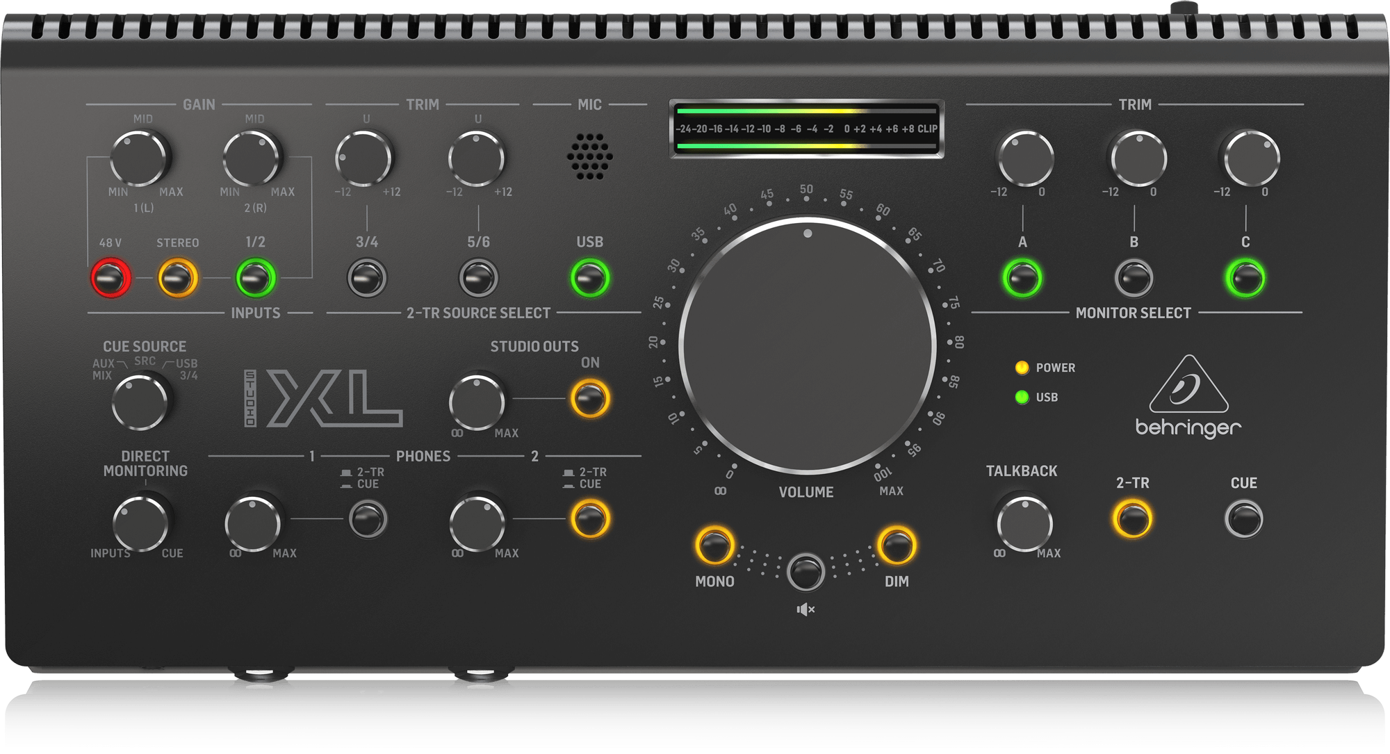
As shown in the image above, monitor controllers can be quite sophisticated in their processing. They often include routing, monitor and source selection and even headphone, subwoofer, and multichannel audio management. However, we will limit our Monitor Controller to four of the most basic functions:
- Dim, which reduces the amplitude of the outgoing audio by a fixed amount
- Cut, which turns off the audio going to the monitors without stopping the playback
- Mid, which adds together the left and right channels of the stereo signal
- Sides, which subtracts the mid signal and reproduces only the side information
Monitor Controller in SystemVerilog
Our Monitor Controller will operate by a) detecting when the buttons on the ZedBoard are pressed, and b) applying the desired processing to the data stream based on which button was pressed.
Detecting Button Presses
Our Monitor Controller will be toggle-based. That means that whenever the user presses one of the four remaining buttons on the ZedBoard (btnu, btnd, btnl and btnr – btnc is already used for triggering the audio codec configuration over SPI) one of the four functions defined above will be enabled or disabled. They are mapped as follows:
- btnu -> Dim
- btnd -> Cut
- btnl -> Mid
- btnd -> Sides
The toggling is achieved by detecting the rising edge of the debounced button signals. Whenever a rising edge is detected, the value of the ‘toggle_[direction]‘ signal is inverted, which gives us the toggling behaviour that we are going for. It is important to react to the edge of the signal and not to its level, otherwise a single press would trigger multiple inversions of the ‘toggle‘ signals. The signal toggling is shown in the code below.
if ((i_btnu == 1\'b1) & (btnu_delay == 1\'b0)) begin
    toggle_up = ~ toggle_up;
end
if ((i_btnd == 1\'b1) & (btnd_delay == 1\'b0)) begin
    toggle_down = ~ toggle_down;
end
if ((i_btnl == 1\'b1) & (btnl_delay == 1\'b0)) begin
    toggle_left = ~ toggle_left;
end
if ((i_btnr == 1\'b1) & (btnr_delay == 1\'b0)) begin
    toggle_right = ~ toggle_right;
end
Calculating the Dim, Cut, Mid and Sides Signals
Once we have our internal toggling signals, we can check their status to enable or disable the function to which they are associated. This is done as follows:
- When the ‘toggle_up’ signal is active (Dim), the data on both channels is divided by four, which is equivalent to applying a gain of -12dB. This is achieved by right-shifting the data twice.
- When the ‘toggle_down‘ signal is active (Cut), the data on both channels is set to zero. This turns off the audio going out to the codec without stopping playback (that is, without stopping the input from the codec).
- When the ‘toggle_left‘ signal is active (Mid) the data on both input channels is added together and the result is divided by two. The result of the division is assigned to both output channels. This gives us a mid (also known as ‘mono‘) signal going to the audio codec.
- When the ‘toggle_left‘ signal is active (Sides), the data on the right input channel is subtracted from the data on the left input channel, and the result is assigned to both output channels. This gives us a ‘side‘ signal, that is, a signal from which all the purely mono information has been removed.
The code below shows the complete RTL description of the Monitor Controller.
module monitor_controller (
    input   logic           i_clock,
    // Audio Data Input
    input   logic [23 : 0]  i_data_left,
    input   logic [23 : 0]  i_data_right,
    input   logic           i_data_valid,
    // Buttons
    input   logic           i_btnu,
    input   logic           i_btnd,
    input   logic           i_btnl,
    input   logic           i_btnr,
    // Audio Data Output
    output  logic [23 : 0]  o_data_left,
    output  logic [23 : 0]  o_data_right,
    output  logic           o_data_valid
);

    timeunit 1ns;
    timeprecision 1ps;

    logic btnu_delay;
    logic btnd_delay;
    logic btnl_delay;
    logic btnr_delay;
    logic toggle_up = 1\'b0;
    logic toggle_down = 1\'b0;
    logic toggle_left = 1\'b0;
    logic toggle_right = 1\'b0;
    always @(posedge i_clock) begin
        btnu_delay <= i_btnu;
        btnd_delay <= i_btnd;
        btnl_delay <= i_btnl;
        btnr_delay <= i_btnr;
        if ((i_btnu == 1\'b1) & (btnu_delay == 1\'b0)) begin
            toggle_up = ~ toggle_up;
        end
        if ((i_btnd == 1\'b1) & (btnd_delay == 1\'b0)) begin
            toggle_down = ~ toggle_down;
        end
        if ((i_btnl == 1\'b1) & (btnl_delay == 1\'b0)) begin
            toggle_left = ~ toggle_left;
        end
        if ((i_btnr == 1\'b1) & (btnr_delay == 1\'b0)) begin
            toggle_right = ~ toggle_right;
        end
        o_data_valid <= i_data_valid;
        o_data_left <= i_data_left;
        o_data_right <= i_data_right;
        // Dim
        if (toggle_up == 1\'b1) begin
            o_data_left <= $signed(i_data_left) >>> 2;
            o_data_right <= $signed(i_data_right) >>> 2;
        end
        // Cut
        if (toggle_down == 1\'b1) begin
            o_data_left <= \'b0;
            o_data_right <= \'b0;
        end
        // Mid
        if (toggle_left == 1\'b1) begin
            o_data_left <= ($signed(i_data_left) + $signed(i_data_right)) >>> 1;
            o_data_right <= ($signed(i_data_left) + $signed(i_data_right)) >>> 1;
        end
        // Sides
        if (toggle_right == 1\'b1) begin
            o_data_left <= ($signed(i_data_left) - $signed(i_data_right));
            o_data_right <= ($signed(i_data_left) - $signed(i_data_right));
        end
    end

endmodule
Notice how when performing the Dim, Mid and Sides functions we need to cast the input channels as signed. This is because the module input signals are declared as ‘logic‘, which is by default unsigned. This is not a problem as long as we treat those signals as a collection of bits, which is what we do when we set them to all zeroes in the Cut function. However, as soon as we do math with them, we need to explicitely tell the synthesis tool that they are signed, so the calculations can be carried out correctly. SystemVerilog handles signed integer signals using two’s complement, the same format used by the audio codec for DA and AD conversion, so no additional signal formatting is required from our logic.
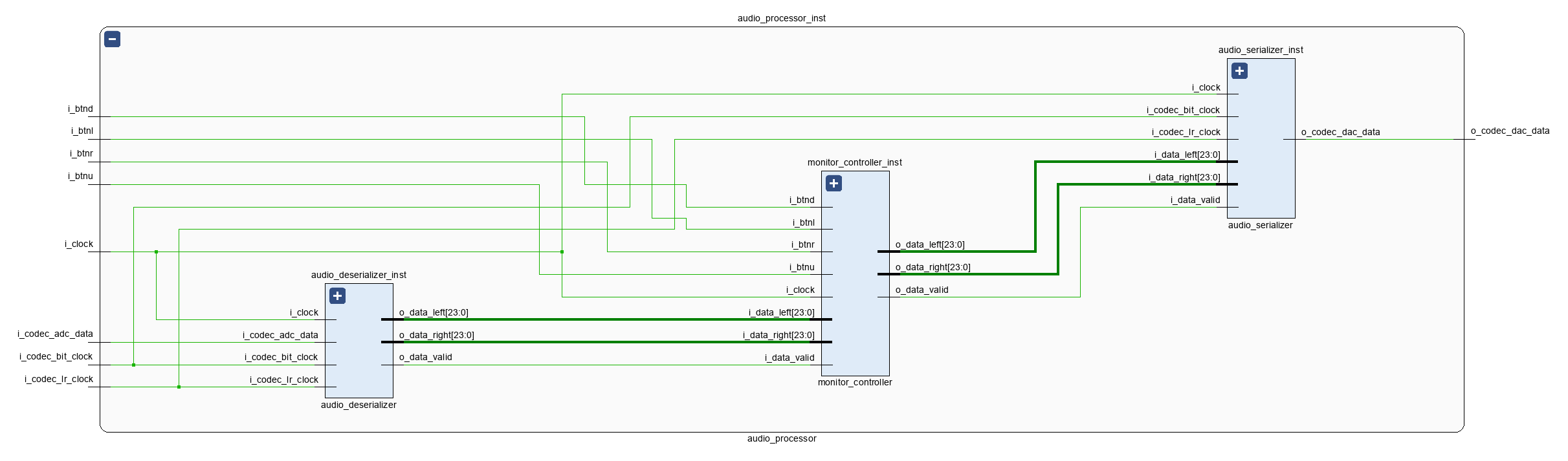
The picture below shows the IO ports of the Monitor Controller and its instantiation within the Audio Processor Core. The Monitor Controller is the first module in our system that modifies the audio data stream, therefore it supports the data/valid communication protocol at both its inputs and its outputs. Because it is meant to process the data only for monitoring purposes, it will normally remain at the end of our processing chain, right before the Audio Serializer.
The priority of each of the four functions in this implementation is given by the order in which they are written in the RTL description. For example, if the user enables both the Dim and Cut functions simultaneously, the Cut will have precedence and the loudspeakers will remain silent. If the Cut function is disabled before the Dim function, the dimmed output will be heard. If the Dim function is disabled before the Cut function, the loudspeakers will continue to be silent, and when the Cut function is disabled, the unprocessed audio (i.e. non-dimmed) will be sent to the monitors. This behaviour is determined by the assignment precedence in SystemVerilog, and we can change it by a) rearranging the order in which each function is descried, or b) using ‘if-else‘ statements to assign priorities to each function.
In the next post we will continue in the audio-processing part of our design by discussing how we can read audio data from a WAV file and use it to test our design in the simulator.
Cheers,
Isaac