In the fourth and final part of this series we will instantiate our dBFS Converter HLS IP core in the LED Meter module. We will also run RTL simulation in Vivado and will generate the new bitstream for our Audio Processor.
Ok, so let’s recap what we have done so far. In the first post of this series we described what dBFS are and introduced the development workflow in Vitis HLS. In the second post we examined in detail the input files for our Vits HLS project and ran the first step in the workflow, C Simulation. In the previous post we ran the other major steps in the Vits HLS workflow (C Synthesis, Co-Simulation, RTL Export) and added the exported IP to the repository of our Audio Processor project in Vivado.
Instantiation
We start by instantiating our dBFS Converter in the LED Meter module. We can find the dBFS Converter IP core in the Vivado IP catalog and add it from there, as shown in the figure below.

After Vivado has generated the IP files we can find the top-level module definition for our dBFS Converter and use it to create an instance of it in the LED Meter. We now need to perform three updates to our LED Meter code.
First, we need drive the inputs of the dBFS Converter with the right data at the right time. We also need to wait until it has finished performing the conversion before we can update the LEDs.
Second, we must add logic to handle the case where the input to the dBFS Converter is zero. Going back to the second installment of the series, the C Simulation revealed that a value of zero in the linear scale, our conversion formula returns 0 dBFS. While this is correct from a purely mathematical standpoint, we would like to have a linear value of zero be equal to +/-1, that is, produce the most negative dBFS possible. But then again, since we are not showing the actual dBFS values in a display but using them to drive the LEDs on the ZedBoard, it will suffice to adjust our RTL description so that a value of zero in the linear scale causes all the LEDs to turn off.
The third and final update to the LED Meter has to do with the comparators that drive the LEDs. Because of the limited resolution that 8 LEDs provide, we will ignore the fractional part of the resturned dBFS values. We will take the integral part and compare it to the 8-step scala that we have defined for our dBFS LED Meter. All three updates to the LED Meter module are shown in the code below.
module led_meter (
    input   logic i_clock,
    // Audio Input
    input   logic signed [23 : 0]   i_data_left,
    input   logic signed [23 : 0]   i_data_right,
    input   logic                   i_data_valid,
    // LED Meter Output
    output  logic [7 : 0]   o_led
);

    timeunit 1ns;
    timeprecision 1ps;

    logic dbfs_converter_start;
    logic dbfs_converter_done;
    logic dbfs_converter_idle;
    logic dbfs_converter_ready;
    logic signed [23 : 0] dbfs_value_integer;
    logic signed [23 : 0] dbfs_value_fraction;
    logic signed [24 : 0]   absolute_mono_sum;
    dbfs_converter_0 dbfs_converter_0_inst (
        .ap_clk         (i_clock),
        .ap_rst         (1\'b0),
        .ap_start       (dbfs_converter_start),
        .ap_done        (dbfs_converter_done),
        .ap_idle        (dbfs_converter_idle),
        .ap_ready       (dbfs_converter_ready),
        .ap_return      ({dbfs_value_integer, dbfs_value_fraction}),
        .linear_value   ({absolute_mono_sum, 24\'h000})
    );

    // Main FSM
    enum logic  [2 : 0]     {IDLE,
                            GET_MONO_SUM,
                            START_DBFS_CONVERSION,
                            GET_DBFS_VALUE,
                            UPDATE_LED} main_fsm_state = IDLE;

    always_ff @(posedge i_clock) begin : main_fsm
        case (main_fsm_state)
            IDLE : begin
                absolute_mono_sum <= \'b0;
                main_fsm_state <= GET_MONO_SUM;
                dbfs_converter_start <= 1\'b0;
            end

            GET_MONO_SUM : begin
                if (i_data_valid == 1\'b1) begin
                    absolute_mono_sum <= (i_data_left + i_data_right) / 2;
                    main_fsm_state <= START_DBFS_CONVERSION;
                end
            end

            START_DBFS_CONVERSION : begin
                if (absolute_mono_sum == 0) begin
                    main_fsm_state <= UPDATE_LED;
                end else begin
                    main_fsm_state <= GET_DBFS_VALUE;
                    dbfs_converter_start <= 1\'b1;
                end
            end

            GET_DBFS_VALUE : begin
                dbfs_converter_start <= 1\'b0;
                if (dbfs_converter_done == 1\'b1) begin
                    main_fsm_state <= UPDATE_LED;
                end
            end

            UPDATE_LED : begin
                // Convert to thermometer code to drive the LEDs
                if (absolute_mono_sum == 0)
                    o_led <= 8\'b0000000;
                else if (dbfs_value_integer > -3)
                    o_led <= 8\'b11111111;
                else if (dbfs_value_integer > -6)
                    o_led <= 8\'b01111111;
                else if (dbfs_value_integer > -9)
                    o_led <= 8\'b00111111;
                else if (dbfs_value_integer > -12)
                    o_led <= 8\'b00011111;
                else if (dbfs_value_integer > -18)
                    o_led <= 8\'b00001111;
                else if (dbfs_value_integer > -24)
                    o_led <= 8\'b00000111;
                else if (dbfs_value_integer > -36)
                    o_led <= 8\'b00000011;
                else if (dbfs_value_integer > -48)
                    o_led <= 8\'b0000001;
                else begin
                    o_led <= 8\'b0000000;
                end
                main_fsm_state <= IDLE;
            end

            default : begin
                main_fsm_state <= IDLE;
            end
        endcase
    end

endmodule
The figure below shows the dBFS Converter IP core instantiated within the LED Meter in the elaborated design.

Simulation
Once we have instantiated the dBFS Converter the next step is to test it in the simulation. This is not required to test the correctness of the dBFS Converter itself, remember that we ran the C/RTL Co-Simulation in the previous post. Still, we want to make sure that the updates we made to the LED Meter are working properly. Also, I just think it will be cool to see an HLS-generated module in an otherwise RTL simulation environment.
As our testbench we will use the SystemVerilog WAVE file reader we introduced in a previous post. The WAVE file reader replaces the incoming audio, so it can be used as the basis for a testbench that directly instantiates the LED Meter as the DUT. The figure below shows the results of the simulation.

The left cursor shows the time where the LED Meter logic initiates the conversion of the very first sample of our test audio file by enabling the ‘dbfs converter start’ input of the dBFS Converter core. At this moment, the input of the dBFS Converter (i.e. the ‘absolute mono sum’ signal) holds the value 1135. The right cursor marks the time at which the dBFS Converter finished its processing and generates an output, as signaled by the enabling of the ‘dbfs converter done‘ signal. This happens 240 clock cycles after the conversion was started, which is the same latency reported by Vitis HLS after the C Synthesis.
Because we mapped the integer and fractional outputs of the dBFS Converter to two different signals (‘dbfs value integer‘ and ‘dbfs value fraction‘) we will create a virtual bus in the waveform window (dBFS Value) to see the complete result. Interestingly, setting the radix of the virtual bus to cover the integral and fractional parts of the signal yields a different result than setting the radix of each signal separately. At any case, we can see that the result of the dBFS conversion matches the output generated by runing the linear-to-dBFS conversion formula on a desktop PC.
Implementation
We now get to implement our design. Finally! After all this we definitely want to see our dBFS Converter placed and routed onto the FPGA. The figure below shows how that looks.
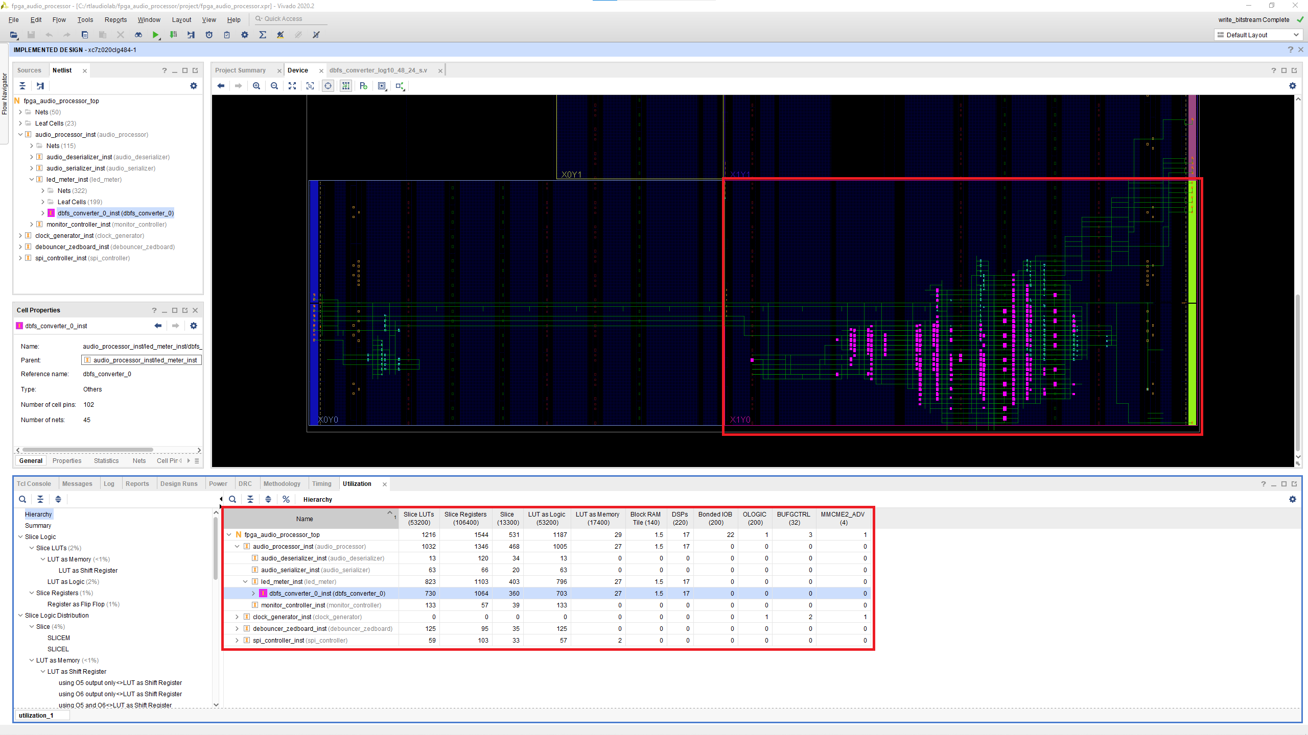
We already know that our logic works, we tested that both in the C/RTL Co-Simulation in Vitis HLS and in the traditional RTL functional simulation in Vivado. So other than making sure that there are no timing or DRC violations in our design (spoiler: it’s all good!) we are interested in the resource utilization.
The Device tab shows the resources used by the dBFS Converter highlighted in purple, and as you can see, there are quite a bit of them. The Utilization tab in the bottom gives us the exact numbers, and the first thing that jumps out is that, as we mentioned in the previous post, Vitis HLS grossly underestimated the amount of DSP Slices that would be required by the dBFS Converter: Vivado ended up using 17, while Vitis HLS estimated that only 4 would be needed. It is very inconvenient that an HLS tool would be that far off in the usage estimation of DSP Slices, as they are perhaps the most critical resource when it comes to implementing DSP algorithms on an FPGA – one of the main application areas of HLS. The rest of the resource estimation is also fairly inaccurate, you can go back to the previous post to compare the Vitis HLS estimates to the final results in Vivado.
Now that we know the resource utilization of our dBFS Converter in absolute terms, let’s see what role it plays in the context of this project and this FPGA. Conveniently, Vivado lets us see the resource utilization of each module as a percentage of the resources available on the FPGA. This is shown in the figure below.
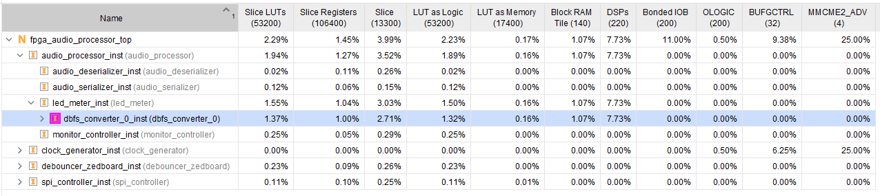
As we can see, the dBFS Converter consumes the most resources in our design, by far. This is especially true when it comes to DSP utilization, which takes 7.7% of all available DSP Slices. This might not seem like much now, but once we start implementing more sophisticated processing we’ll see that this is a large amount of resources, to be consumed by a small and relatively unimportant module.
It is fair to ask ourselves whether it makes sense to perform the conversion to dBFS on the programmable logic at runtime. When it comes to using the dBFS values in the LED meter, the answer probably is no, it doesn’t. There are at least two better ways to implement this functionality:
- If we have a fixed dBFS-to-LED mapping (which is the case in most meters) we can calculate the linear values that correspond to the dBFS ranges in the RTL code as parameters and continue to use the linear scale in the LED Meter. This is likely the way the LED Meter will work in the future.
- If we need to adjust the dBFS-to-LED conversion ranges at runtime (which would be a very unusual requirement) and we can use a processor, we can have the software calculate the linear thresholds from dBFS values and send them to the comparators in the LED Meter.
Leaving these practicalities aside, I believe this has been a great project to get started with Vitis HLS, and HLS-based designs in general – not too complicated as to become overwhelming, yet not too trivial as to become uninteresting. We will use this foundation to take on more challenging designs in the future.
Cheers,
Isaac