In this post we will take our first steps into the world of floating-point audio processing with FPGAs by converting our fixed-point audio samples to floating point and performing a basic delay operation.
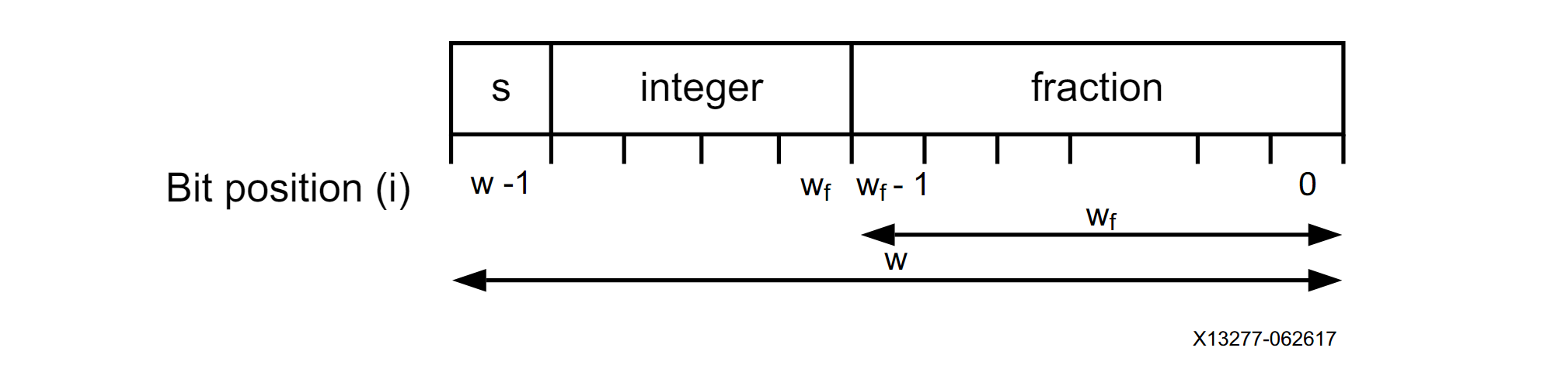
Most processing in FPGA designs is done using fixed-point number representation, and most of those fixed-point binary signals contain only an integer part, with no fractional bits. As we discussed in a previous post, the two‘s complement format is used to represent negative numbers. The fixed-point binary representation is shown in the figure below, where ‘w’ represents the total number of bits and ‘wf’ represents the number of bits representing the fractional part. The number of bits representing the integer part is equal to w – wf.
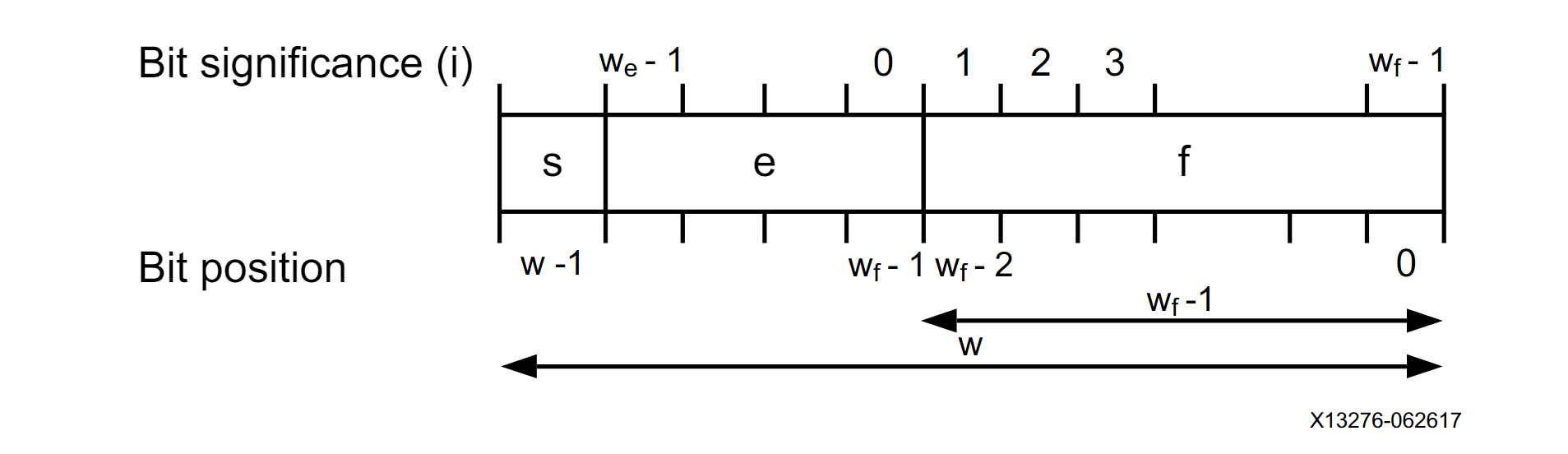
On the other hand, the floating-point number representation uses an exponent and a fractional part (also known as the significand) to describe numbers in scientific notation. The binary representation of floating-point numbers has been defined in the 754-2019 – IEEE Standard for Floating-Point Arithmetic and is shown in the figure below.
Pros and Cons of Floating-Point Processing in FPGAs
There are several advantages to working with floating-point numbers in our Audio Processor. Most resources on audio processing algorithms use floating-point representation, so it would be more straightforward to implement many algorithms on the FPGA from their high-level representation.
Because floating-point representation covers a much larger dynamic range than fixed-point for the same number of bits, it is more forgiving when it comes to performing calculations between very large and very small numbers. In that vein, the extended dynamic range frees us from having to keep track of the bit width of the fixed-point signals after each operation, which can dramatically simplify the design process. The dynamic-range adjustments have been built into the floating-point arithmetic.
In the specific case of audio processing, the floating-point representation allows for a lot of headroom between the different processing stages (actually, it has more headroom than would ever be realistically required for industry-standard 24-bit audio codecs, or even bleeding-edge 32-bit versions). This is a great advantage for potential users, who have now gotten used to not being super careful about clipping between processing stages. As long as the output of the system is reduced to a range suitable for the DAC, everything will be fine.
Now, if floating point processing has these awesome advantages, why isn’t used in every single design out there? The main reasons are increased resource utilization and power consumption: floating-point arithmetic is much more computationally demanding than its fixed-point counterpart, often prohibitively so. Luckily for us, these are not properties that we would like to optimize at this stage. We should also keep in mind that, while the increased dynamic range can help simplify the design process, in can come at the cost of a loss of precision that can be unacceptable for certain types of processing.
Floating-Point Conversion and Arithmetic
The Xilinx IP catalog includes modules that make it easier to start working with floating-point numbers. The Floating-Point Operator IP Core can be configured not only to perform several common arithmetic and logical operations in floating point, but also to carry out the conversion from fixed- to floating-point and back.
We start by generating a core that will convert our 24-bit signed integer representation to a single-precision (32-bit) floating-point number. The Floating-Point Operator uses the AXI4-Stream protocol for transferring data, in this case we won’t need to apply any backpressure, so we will disable the TREADY signal. This will leave us with a similar interface to the one we defined in our Audio (De)Serializer modules, using only two signals: one ‘data’ signal, which contains our audio sample, and one ‘valid‘ signal, which indicates when the value in the corresponding data bus is valid.
We need to keep in mind that, unlike the protocol we defined for the (De)Serializer modules, the AXI4-Stream dictates that the values in the data bus are only valid while the TVALID signal is enabled. This means that we need to store the output of the Floating-Point Operator so we can use it later.
To build our floating-point processing path, we instantiate the fixed-to-float converter directly after the Deserializer module. We will instantiate one for each channel (more on that later) and the output will be connected to a delay module. We will explore the implementation of a delay effect in detail later, for now we will just use it to get a sense of what the floating-point processing looks like in an FPGA design.
Our delay takes the value of one sample, applies a gain of less than one to it and adds it to the next sample. This is the basic operating principle of a feedback delay. Because we are delaying by exactly one sample, the effect will not be audible. Again, we just want to have a working floating-point processing module for now. The delay logic is implemented as an FSM that performs the multiplication and addition using the Floating-Point Operator. The RTL description for the Delay module is shown below.
module delay (
    input   logic           i_clock,
    input   logic [31 : 0]  i_data_left,
    input   logic [31 : 0]  i_data_right,
    input   logic           i_data_valid,
    output  logic [31 : 0]  o_data_left,
    output  logic [31 : 0]  o_data_right,
    output  logic           o_data_valid
);


    logic           fp_mult_valid_out;
    logic [31 : 0]  fp_mult_data_out;
    logic [31 : 0]  multiplier_data_in;
    logic           multiplier_data_valid;
    logic [31 : 0]  feedback_gain = 31\'b00111111010000000000000000000000;
    fp_multiplier fp_multiplier_inst (
        .aclk                   (i_clock),
        .s_axis_a_tvalid        (multiplier_data_valid),
        .s_axis_a_tdata         (multiplier_data_in),
        .s_axis_b_tvalid        (multiplier_data_valid),
        .s_axis_b_tdata         (feedback_gain),
        .m_axis_result_tvalid   (fp_mult_valid_out),
        .m_axis_result_tdata    (fp_mult_data_out)
    );

    logic           fp_adder_valid_out;
    logic [31 : 0]  fp_adder_data_out;
    logic [31 : 0]  adder_data_a_in;
    logic [31 : 0]  adder_data_b_in;
    logic           adder_data_valid;
    fp_adder fp_adder_inst (
        .aclk                   (i_clock),
        .s_axis_a_tvalid        (adder_data_valid),
        .s_axis_a_tdata         (adder_data_a_in),
        .s_axis_b_tvalid        (adder_data_valid),
        .s_axis_b_tdata         (adder_data_b_in),
        .m_axis_result_tvalid   (fp_adder_valid_out),
        .m_axis_result_tdata    (fp_adder_data_out)
    );

    // Main FSM
    logic [31 : 0] delayed_sample_left  = \'b0;      // Positive zero in floating point
    logic [31 : 0] delayed_sample_right = \'b0;      // Positive zero in floating point
    logic [31 : 0] fetch_sample_right  = \'b0;       // Positive zero in floating point

    enum logic [2 : 0]  {IDLE,
                        MULTIPLY_LEFT,
                        ADD_LEFT,
                        MULTIPLY_RIGHT,
                        ADD_RIGHT} fsm_state = IDLE;

    always_ff @(posedge i_clock) begin
        case (fsm_state)
            IDLE : begin
                multiplier_data_valid <= 1\'b0;
                adder_data_valid <= 1\'b0;
                o_data_valid <= \'b0;
                if (i_data_valid == 1\'b1) begin
                    multiplier_data_in <= i_data_left;
                    fetch_sample_right <= i_data_right;
                    multiplier_data_valid <= 1\'b1;
                    fsm_state <= MULTIPLY_LEFT;
                end
            end

            MULTIPLY_LEFT : begin
                multiplier_data_valid <= 1\'b0;
                if (fp_mult_valid_out == 1\'b1) begin
                    adder_data_a_in <= delayed_sample_left;
                    adder_data_b_in <= fp_mult_data_out;
                    adder_data_valid <= 1\'b1;
                    fsm_state <= ADD_LEFT;
                end
            end

            ADD_LEFT : begin
                adder_data_valid <= 1\'b0;
                if (fp_adder_valid_out == 1\'b1) begin
                    o_data_left <= fp_adder_data_out;
                    delayed_sample_left <= fp_adder_data_out;
                    multiplier_data_in <= fetch_sample_right;
                    multiplier_data_valid <= 1\'b1;
                    fsm_state <= MULTIPLY_RIGHT;
                end
            end

            MULTIPLY_RIGHT : begin
                multiplier_data_valid <= 1\'b0;
                if (fp_mult_valid_out == 1\'b1) begin
                    adder_data_a_in <= delayed_sample_right;
                    adder_data_b_in <= fp_mult_data_out;
                    adder_data_valid <= 1\'b1;
                    fsm_state <= ADD_RIGHT;
                end
            end

            ADD_RIGHT : begin
                adder_data_valid <= 1\'b0;
                if (fp_adder_valid_out == 1\'b1) begin
                    o_data_right <= fp_adder_data_out;
                    delayed_sample_right <= fp_adder_data_out;
                    o_data_valid <= 1\'b1;
                    fsm_state <= IDLE;
                end
            end

            default : begin
                fsm_state <= IDLE;
            end
        endcase
    end

endmodule
The FSM is responsible for setting the correct input operands, enabling the TVALID signal of the adder and multiplier, and monitoring the TVALID outputs to make sure that the results are sampled at the correct time. Notice that we use one adder and one multiplier for both channels, as this is a powerful use case for FPGAS in audio processing: often the latency of the audio processing is quite small when compared with the audio sample rate, so the same logic can be reused for processing multiple channels. We could have also done this multiplexing for the fixed-to-float conversion. Perhaps we will at some point.
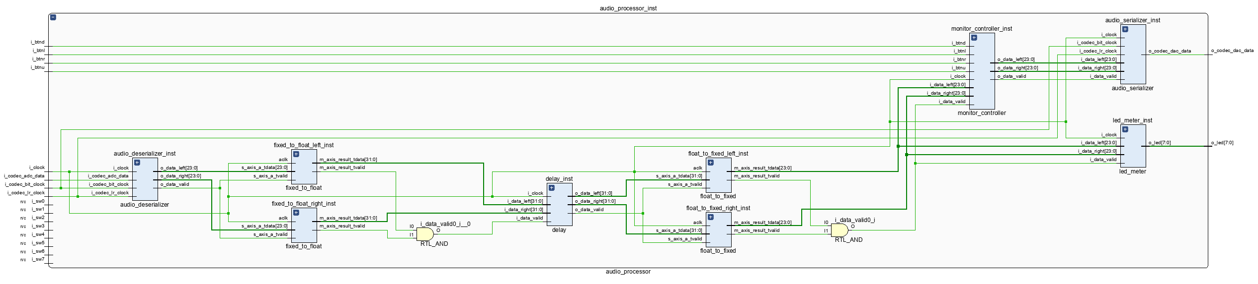
We now need to convert the floating-point output of our delay module back to fixed point. We set the Floating-Point Operator to float-to-fixed and configure it to convert the 32-bit floating-point audio data into 24-bit fixed-point representation. This conversion will usually take place at the end of the processing chain before the data is sent to the Monitor Controller. The updated pipeline of the Audio Processor is shown in the figure below.
Resource Utilization of the Floating-Point Arithmetic
After updating our Audio Processor core with the floating-point conversion and arithmetic, we are ready to run synthesis and implementation. The implemented design with the resource utilization for the floating-point-related logic is shown in the figure below.
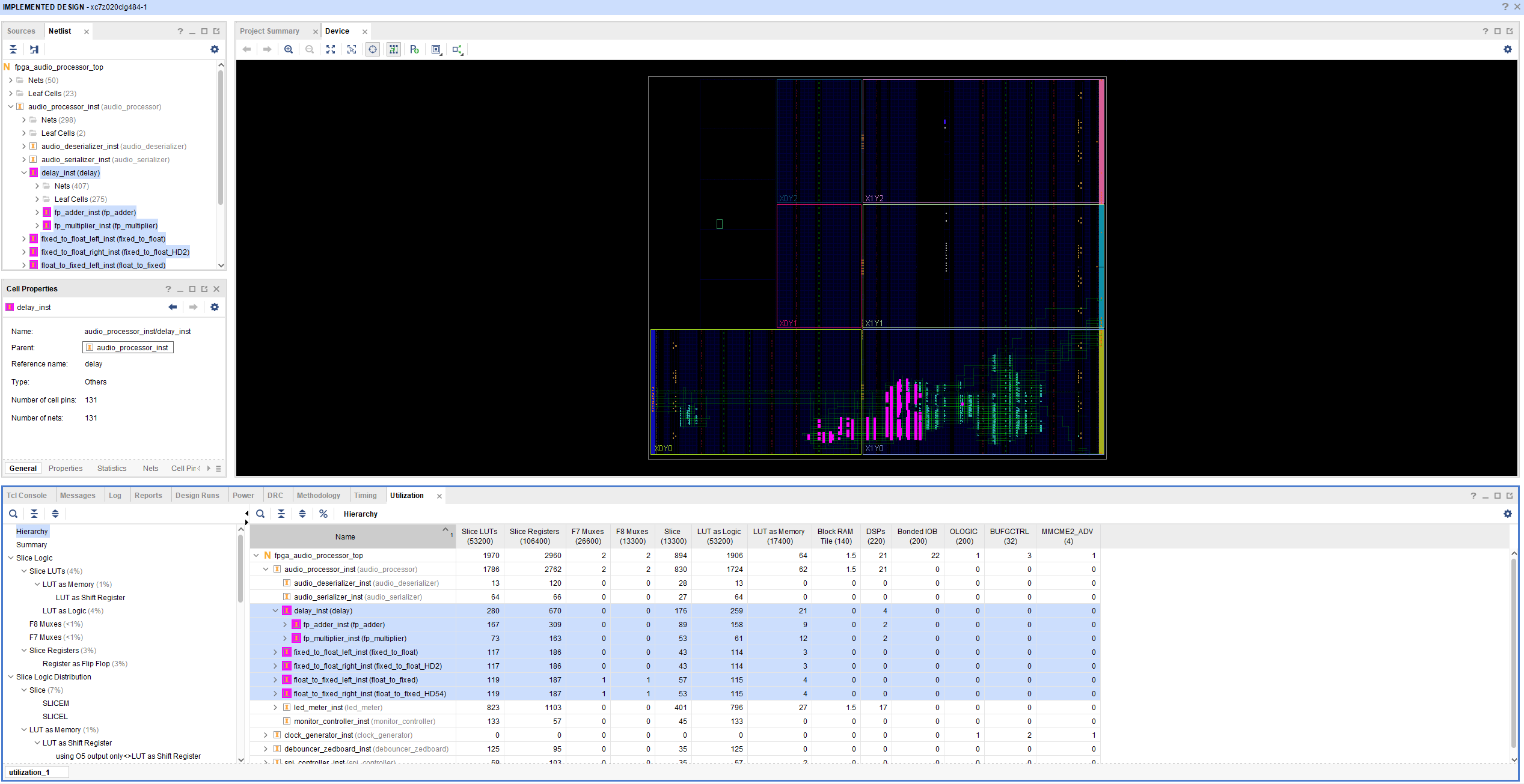
The figure below shows the same utilization as a percentage of the resources available in the Zynq.
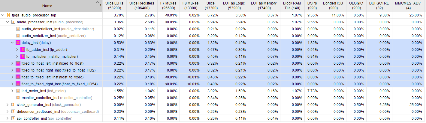
As we can see, the floating-point logic uses two DSP slices for multiplication and two for addition. That’s… a lot? Not that many? There’s no way to know without providing more context. Hoy much processing cores do we want to instantiate at the same time? For how many channels? How big a device can we afford? How much development time are we willing to invest? These factors all play an important role in deciding whether a design approach is appropriate for a project.
And for the Audio Processor project, I’m happy to move forward with floating-point processing, at least for now. The ability to quickly go from high-level algorithms to their FPGA implementation without much hassle is the deciding factor for me. Seeing that it can be done without sacrificing (attention: highly subjective criteria incoming) that many resources is very encouraging. Granted, a delay module is about as simple as it gets algorithmically speaking: we only need one multiplication and one addition. We’ll see how floating-point processing fares when we get into the more complicated stuff.
For now though, we will focus on expanding this delay implementation so that we can, you know, hear it. We’ll dive in in the next post.
Cheers,
Isaac