In this post we will go over the implementation of a stereo delay effect for our FPGA Audio Processor.
In the previous post we took our first steps into the world of time-based processing with a mono delay. Expanding that design to support stereo audio will open new possibilities for creating interesting effects. Let’s get started.
From Mono to Stereo
As a quick reminder, here’s what a mono feedback delay looks like:
Adding stereo support to our mono Delay is relatively straightforward. The core idea is that, instead of converting the incoming samples to mono and storing them in a single circular buffer, we create one buffer per channel. The way in which we keep track of the write and read pointers, apply the delay gain and implement a feedforward or a feedback architecture remains unchanged, we’ll just have two of everything now.
However, expanding our mono Delay to stereo does bring some changes to the architecture and resources of our logic. Because we don’t have to convert the incoming stereo data to mono, we can get rid of the floating-point division logic altogether. On the other hand, we must perform the multiplication and addition in the delay line for both channels. However, the biggest difference in terms of resource utilization is given by the doubling of the memory needed for the delay lines. There is no way around this though, we need a delay line for each channel if we want to have a Delay effect in the first place. We’ll come back to this later.
Because the mono conversion is no longer needed, we can simplify the logic in the Main FSM so that it better follows the logical flow of the stereo Delay effect. The Main FSM will now:
- Fetch the audio samples for the left and right channels. In a feedforward architecture, they are also added to the circular buffer here.
- Read the next sample from the left buffer and apply the delay gain to it.
- Read the next sample from the right buffer and apply the delay gain to it.
- Add the left delay sample to the real-time sample and assign it to the output. In a feedback architecture, the outgoing left sample is also added to the circular buffer here.
- Add the right delay sample to the real-time sample and assign it to the output. In a feedback architecture, the outgoing right sample is also added to the circular buffer here.
- Mark the outputs as valid and go back to waiting for the next samples.
As a potential optimization, performing the addition for each channel directly after applying the delay gain would probably allow us to shave off one signal (for each channel) that is currently needed for intermediate storage. The RTL description of our stereo Delay is shown below.
module delay #(
    parameter string DELAY_TYPE = "STEREO",         // "STEREO"
    parameter string FEED_TYPE = "FEEDBACK"         // "FEEDBACK", "FEEDFORWARD"
    )(
    input   logic           i_clock,
    input   logic [31 : 0]  i_data_left,
    input   logic [31 : 0]  i_data_right,
    input   logic           i_data_valid,
    output  logic [31 : 0]  o_data_left,
    output  logic [31 : 0]  o_data_right,
    output  logic           o_data_valid
);

    // Floating-point Multiplier
    logic           fp_mult_valid_out;
    logic [31 : 0]  fp_mult_data_out;
    logic [31 : 0]  fp_multiplier_data_a_in;
    parameter logic [31 : 0]  feedback_gain = 31'b00111111010000000000000000000000;     // 0.75
    logic           fp_multiplier_data_valid;
    fp_multiplier fp_multiplier_inst(
        .aclk                   (i_clock),
        .s_axis_a_tvalid        (fp_multiplier_data_valid),
        .s_axis_a_tdata         (fp_multiplier_data_a_in),
        .s_axis_b_tvalid        (fp_multiplier_data_valid),
        .s_axis_b_tdata         (feedback_gain),
        .m_axis_result_tvalid   (fp_mult_valid_out),
        .m_axis_result_tdata    (fp_mult_data_out)
    );

    // Floating-point Adder
    logic           fp_adder_valid_out;
    logic [31 : 0]  fp_adder_data_out;
    logic [31 : 0]  fp_adder_data_a_in;
    logic [31 : 0]  fp_adder_data_b_in;
    logic           fp_adder_data_valid;
    fp_adder fp_adder_inst(
        .aclk                   (i_clock),
        .s_axis_a_tvalid        (fp_adder_data_valid),
        .s_axis_a_tdata         (fp_adder_data_a_in),
        .s_axis_b_tvalid        (fp_adder_data_valid),
        .s_axis_b_tdata         (fp_adder_data_b_in),
        .m_axis_result_tvalid   (fp_adder_valid_out),
        .m_axis_result_tdata    (fp_adder_data_out)
    );

    // Circular Buffer for the Left Channel
    logic           delay_buffer_left_wr_en;
    logic [13 : 0]  delay_buffer_left_addra = 'b0;
    logic [31 : 0]  delay_buffer_left_dina;
    logic [13 : 0]  delay_buffer_left_addrb = 14'd1;
    logic [31 : 0]  delay_buffer_left_doutb;
    delay_circular_buffer delay_circular_buffer_left_inst(
        .clka   (i_clock),
        .wea    (delay_buffer_left_wr_en),
        .addra  (delay_buffer_left_addra),
        .dina   (delay_buffer_left_dina),
        .clkb   (i_clock),
        .addrb  (delay_buffer_left_addrb),
        .doutb  (delay_buffer_left_doutb)
    );

    // Circular Buffer for the Right Channel
    logic           delay_buffer_right_wr_en;
    logic [13 : 0]  delay_buffer_right_addra = 'b0;
    logic [31 : 0]  delay_buffer_right_dina;
    logic [13 : 0]  delay_buffer_right_addrb = 14'd1;
    logic [31 : 0]  delay_buffer_right_doutb;
    delay_circular_buffer delay_circular_buffer_right_inst(
        .clka   (i_clock),
        .wea    (delay_buffer_right_wr_en),
        .addra  (delay_buffer_right_addra),
        .dina   (delay_buffer_right_dina),
        .clkb   (i_clock),
        .addrb  (delay_buffer_right_addrb),
        .doutb  (delay_buffer_right_doutb)
    );

    // Main FSM
    enum logic [2 : 0]  {IDLE,
                        DELAY_GAIN_LEFT,
                        DELAY_GAIN_RIGHT,
                        ADD_OUTPUT_LEFT,
                        ADD_OUTPUT_RIGHT,
                        GENERATE_OUTPUT} fsm_state = IDLE;
    logic [31 : 0]  mono_sample;
    logic [31 : 0]  current_sample_left;
    logic [31 : 0]  current_sample_right;
    logic [31 : 0]  sample_left_aux;
    logic [31 : 0]  sample_right_aux;
    logic           ping_pong_left_buffer_active = 1'b1;

    always_ff @(posedge i_clock) begin
        case (fsm_state)
            IDLE : begin
                fp_adder_data_valid <= 1'b0;
                delay_buffer_left_wr_en <= 1'b0;
                delay_buffer_right_wr_en <= 1'b0;
                o_data_valid <= 1'b0;
                if (i_data_valid == 1'b1) begin
                    current_sample_left <= i_data_left;
                    current_sample_right <= i_data_right;
                    if (FEED_TYPE == "FEEDFORWARD") begin
                        delay_buffer_left_dina <= i_data_left;
                        delay_buffer_left_wr_en <= 1'b1;
                        delay_buffer_right_dina <= i_data_right;
                        delay_buffer_right_wr_en <= 1'b1;
                    end
                    fp_multiplier_data_a_in <= delay_buffer_left_doutb;         // Start the delay gain on the left channel
                    fp_multiplier_data_valid <= 1'b1;
                    if (delay_buffer_left_addra == 12000) begin                 // Wrap the pointers around if they reach the end of the buffer
                        delay_buffer_left_addra <= 0;
                        delay_buffer_left_addrb <= 1;
                    end
                    if (delay_buffer_right_addra == 16381) begin                // Wrap the pointers around if they reach the end of the buffer
                        delay_buffer_right_addra <= 0;
                        delay_buffer_right_addrb <= 1;
                    end
                    fsm_state <= DELAY_GAIN_LEFT;
                end
            end

            DELAY_GAIN_LEFT : begin
                delay_buffer_left_wr_en <= 1'b0;
                delay_buffer_right_wr_en <= 1'b0;
                fp_multiplier_data_valid <= 1'b0;
                if (fp_mult_valid_out == 1'b1) begin
                    sample_left_aux <= fp_mult_data_out;
                    fp_multiplier_data_a_in <= delay_buffer_right_doutb;        // Start the delay gain on the right channel
                    fp_multiplier_data_valid <= 1'b1;
                    fsm_state <= DELAY_GAIN_RIGHT;
                end
            end

            DELAY_GAIN_RIGHT : begin
                fp_multiplier_data_valid <= 1'b0;
                if (fp_mult_valid_out == 1'b1) begin
                    sample_right_aux <= fp_mult_data_out;
                    fp_adder_data_a_in <= current_sample_left;                  // Start adding the current left sample with the delayed one
                    fp_adder_data_b_in <= sample_left_aux;
                    fp_adder_data_valid <= 1'b1;
                    fsm_state <= ADD_OUTPUT_LEFT;
                end
            end

            ADD_OUTPUT_LEFT : begin
                fp_adder_data_valid <= 1'b0;
                if (fp_adder_valid_out == 1'b1) begin
                    o_data_left <= fp_adder_data_out;
                    if (FEED_TYPE == "FEEDBACK") begin
                        delay_buffer_left_dina <= fp_adder_data_out;
                        delay_buffer_left_wr_en <= 1'b1;
                    end;
                    fp_adder_data_a_in <= current_sample_right;                 // Start adding the current right sample with the delayed one
                    fp_adder_data_b_in <= sample_right_aux;
                    fp_adder_data_valid <= 1'b1;
                    fsm_state <= ADD_OUTPUT_RIGHT;
                end
            end

            ADD_OUTPUT_RIGHT : begin
                fp_adder_data_valid <= 1'b0;
                delay_buffer_left_wr_en <= 1'b0;
                if (fp_adder_valid_out == 1'b1) begin
                    o_data_right <= fp_adder_data_out;
                    if (FEED_TYPE == "FEEDBACK") begin
                        delay_buffer_right_dina <= fp_adder_data_out;
                        delay_buffer_right_wr_en <= 1'b1;
                    end;
                    o_data_valid <= 1'b1;
                    delay_buffer_left_addra <= delay_buffer_left_addra + 1;     // Increment the write and read pointers
                    delay_buffer_left_addrb <= delay_buffer_left_addrb + 1;
                    delay_buffer_right_addra <= delay_buffer_right_addra + 1;
                    delay_buffer_right_addrb <= delay_buffer_right_addrb + 1;
                    fsm_state <= IDLE;
                end;
            end

            default : begin
                fsm_state <= IDLE;
            end
        endcase
    end

endmodule
Simulation and Implementation
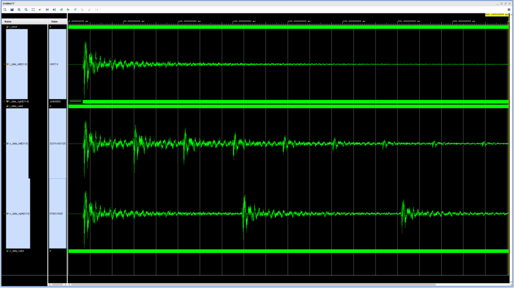
We are now ready to simulate our new stereo Delay. For this test we set the left buffer pointers to wrap around after 2000 samples (~45 milliseconds), and the right buffer pointers to wrap around after 6381 samples (~145 milliseconds). Thus, we expect to see about three taps of the left delay for every tap of the right channel. We’ll use the same mono snare hit that we used in the previous post for easier visualization. The result of the simulation is shown in the figure below.
We can see that the taps in the left channel decay more rapidly than in the right channel. This makes sense, as they are generated from the same input signal, but the feedback delay is applied three times as often to the left channel.
Let’s turn our attention to the resource utilization of our stereo delay. The figure below shows how much of the on-chip Block RAMs are used by the stereo Delay, more than 20%! This is surely not a scalable solution for larger delay lines, which can easily require storing several seconds worth of audio samples. The solution here is to move most of the delayed samples to off-chip memory, and only keep the last few hundreds in the Block RAM. Off-chip memory is usually plentiful compared with on-chip Block RAM’s (for our FPGA/board pair we are talking gigabytes vs. megabits), but it comes at the expense of more complex logic and higher memory bandwidth for reading from and writing to external memory. Having said that, once we have managed the memory accesses, memory bandwidth in an audio application with low channel counts will rarely be a bottleneck.
Multi-tap Delay
Before we wrap up our discussion of delays, there is one more type I’d like to mention: the multi-tap delay.
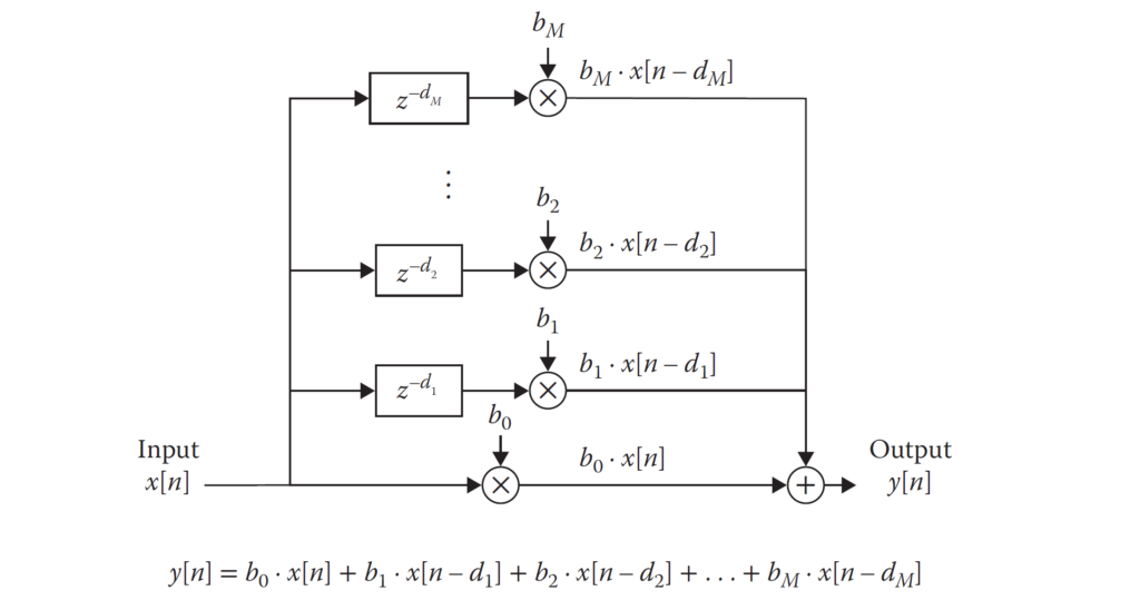
In a feedforward delay we have exactly one tap per channel. In a feedback delay we have several (in theory infinite) taps, but we can’t control exactly how many of them we’ll hear, they decay on their own after we’ve set the feedback gain. If we would like to specify the exact number of taps that we want to hear, we need to use a multi-tap delay, as shown in the figure below.
A multi-tap delay consists of several feedforward delay lines, each with its own delay time and, if so desired, its own feedback gain. This architecture is fairly straightforward, but as you can probably guess, requires several times more storage than a single delay line.
That’s it for our exploration of delays. In the next post we will update our LED Meter to support stereo display.
Cheers,
Isaac


