In this post we will go over the implementation of an RMS meter on an FPGA.
In our original LED Meter we measured the magnitude of our incoming audio signal by extracting the absolute value of each sample. When we expanded the LED Meter to support stereo inputs, this fundamental measurement strategy remained the same. However, this is not the only way to measure an audio signal. Today we will discuss another way to measure the magnitude of a signal: the Root Mean Square (RMS) measurement.
RMS Value in a Nutshell
The RMS value of a signal is calculated by averaging the square values of its samples over time and then extracting the square root of the result, as given by this formula:
In electrical engineering, the RMS value of an AC signal tells how much energy it contains. More specifically, it tells us the value that a DC signal would need to have in order to dissipate the same amount of power over a resistor as the AC signal that we are measuring. Because it measures energy, the RMS value of an audio signal has been historically used as a proxy for its perceived loudness.
By changing the length of the averaging window, we can adjust the sensitivity of our RMS Meter to sudden changes in the amplitude of the audio signal.
RMS Measurement in SystemVerilog
We will stick to floating-point processing for our RMS Meter so that we can use it as a building block for any algorithm that requires the magnitude of the signal as an input. We will use the same approach from our mono and stereo delays, where we rely on Xilinx’s Floating-Point Operator IP cores to perform the arithmetic calculations, and we implement a custom FSM to provide the inputs and wait for the outputs. Also like for the delay logic, we need a circular buffer to store the last N samples that we will use to calculate the RMS value. We will store 1024 samples, but the actual value is not important for now, as it can be easily parameterized later. We also introduced the circular buffer when describing the mono delay effect.
So how do we go about implementing the RMS formula above? A naive approach would be to run the entire calculation with each new sample, but that would be extremely inefficient: we would have to perform 1024 multiplications, 1023 additions, one division and one square root operation at every cycle. Instead, we will use an accumulator that keeps the running sum of the averaged samples. At each sample we will:
- Square the newest (incoming) sample, add it to the accumulator and store it in the circular buffer
- Fetch the oldest sample from the circular buffer (which is already squared) and subtract it from the accumulator
- Divide the accumulator by 1024 and store the result in a different signal (we need to keep the running sum in the accumulator!)
- Extract the square root from the result of the division
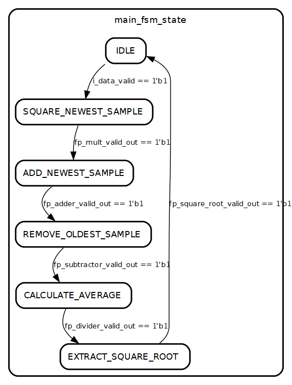
The figure below shows the state diagram for the FSM that performs the RMS calculation.
The source code for the FSM is shown below.
module rms_meter (
    input   logic i_clock,
    // Audio Input
    input   logic   [31 : 0]    i_data,
    input   logic               i_data_valid,
    // RMS Value Output
    output  logic   [31 : 0]    o_rms_value,
    output  logic               o_rms_value_valid
);

    timeunit 1ns;
    timeprecision 1ps;

    localparam shortreal BUFFER_SIZE = 32'h44800000;    // 1024

    // Buffer
    logic           buffer_wr_en = 1'b0;
    logic [9 : 0]   buffer_data_in_addr = 'b0;
    logic [31 : 0]  buffer_data_in = 'b0;
    logic [9 : 0]   buffer_data_out_addr = 'b0;
    logic [31 : 0]  buffer_data_out;
    rms_meter_buffer rms_meter_buffer_inst(
        .clka   (i_clock),
        .wea    (buffer_wr_en),
        .addra  (buffer_data_in_addr),
        .dina   (buffer_data_in),
        .clkb   (i_clock),
        .addrb  (buffer_data_out_addr),
        .doutb  (buffer_data_out)
    );

    // Floating-point Multiplier
    logic           fp_mult_valid_in;
    logic [31 : 0]  fp_mult_data_a;
    logic [31 : 0]  fp_mult_data_b;
    logic           fp_mult_valid_out;
    logic [31 : 0]  fp_mult_data_out;
    fp_multiplier fp_multiplier_inst(
        .aclk                   (i_clock),
        .s_axis_a_tvalid        (fp_mult_valid_in),
        .s_axis_a_tdata         (fp_mult_data_a),
        .s_axis_b_tvalid        (fp_mult_valid_in),
        .s_axis_b_tdata         (fp_mult_data_b),
        .m_axis_result_tvalid   (fp_mult_valid_out),
        .m_axis_result_tdata    (fp_mult_data_out)
    );

    // Floating-point Adder
    logic           fp_adder_valid_in;
    logic [31 : 0]  fp_adder_data_a;
    logic [31 : 0]  fp_adder_data_b;
    logic           fp_adder_valid_out;
    logic [31 : 0]  fp_adder_data_out;
    fp_adder fp_adder_inst(
        .aclk                   (i_clock),
        .s_axis_a_tvalid        (fp_adder_valid_in),
        .s_axis_a_tdata         (fp_adder_data_a),
        .s_axis_b_tvalid        (fp_adder_valid_in),
        .s_axis_b_tdata         (fp_adder_data_b),
        .m_axis_result_tvalid   (fp_adder_valid_out),
        .m_axis_result_tdata    (fp_adder_data_out)
    );

    // Floating-point Subtractor
    logic           fp_subtractor_valid_in;
    logic [31 : 0]  fp_subtractor_data_a;
    logic [31 : 0]  fp_subtractor_data_b;
    logic           fp_subtractor_valid_out;
    logic [31 : 0]  fp_subtractor_data_out;
    fp_subtractor fp_subtractor_inst(
        .aclk                   (i_clock),
        .s_axis_a_tvalid        (fp_subtractor_valid_in),
        .s_axis_a_tdata         (fp_subtractor_data_a),
        .s_axis_b_tvalid        (fp_subtractor_valid_in),
        .s_axis_b_tdata         (fp_subtractor_data_b),
        .m_axis_result_tvalid   (fp_subtractor_valid_out),
        .m_axis_result_tdata    (fp_subtractor_data_out)
    );

    // Floating-point Divider
    logic           fp_divider_valid_in;
    logic [31 : 0]  fp_divider_data_a;
    logic [31 : 0]  fp_divider_data_b;
    logic           fp_divider_valid_out;
    logic [31 : 0]  fp_divider_data_out;
    fp_divider fp_divider_inst(
        .aclk                   (i_clock),
        .s_axis_a_tvalid        (fp_divider_valid_in),
        .s_axis_a_tdata         (fp_divider_data_a),
        .s_axis_b_tvalid        (fp_divider_valid_in),
        .s_axis_b_tdata         (fp_divider_data_b),
        .m_axis_result_tvalid   (fp_divider_valid_out),
        .m_axis_result_tdata    (fp_divider_data_out)
    );

    // Floating-point Square Root
    logic           fp_square_root_valid_in;
    logic [31 : 0]  fp_square_root_data_in;
    logic [31 : 0]  fp_square_root_data_out;
    fp_square_root fp_square_root_inst(
        .aclk                   (i_clock),
        .s_axis_a_tvalid        (fp_square_root_valid_in),
        .s_axis_a_tdata         (fp_square_root_data_in),
        .m_axis_result_tvalid   (fp_square_root_valid_out),
        .m_axis_result_tdata    (fp_square_root_data_out)
    );

    // Main FSM
    enum logic [2 : 0]  {IDLE,
                        SQUARE_NEWEST_SAMPLE,
                        ADD_NEWEST_SAMPLE,
                        FETCH_OLDEST_SAMPLE,
                        REMOVE_OLDEST_SAMPLE,
                        CALCULATE_AVERAGE,
                        EXTRACT_SQUARE_ROOT} main_fsm_state = IDLE;

    logic [31 : 0] accumulator = 'b0;
    logic [31 : 0] aux = 'b0;

    always_ff @(posedge i_clock) begin : main_fsm
        buffer_data_out_addr <= buffer_data_in_addr + 1;
        case (main_fsm_state)
            IDLE : begin
                o_rms_value_valid <= 1'b0;
                buffer_wr_en <= 1'b0;
                fp_mult_valid_in <= 1'b0;
                fp_adder_valid_in <= 1'b0;
                fp_subtractor_valid_in <= 1'b0;
                fp_divider_valid_in <= 1'b0;
                fp_square_root_valid_in <= 1'b0;
                if (i_data_valid == 1'b1) begin
                    fp_mult_valid_in <= 1'b1;
                    fp_mult_data_a <= i_data;
                    fp_mult_data_b <= i_data;
                    buffer_data_in_addr <= buffer_data_in_addr + 1;
                    main_fsm_state <= SQUARE_NEWEST_SAMPLE;
                end
            end

            SQUARE_NEWEST_SAMPLE : begin
                fp_mult_valid_in <= 1'b0;
                if (fp_mult_valid_out == 1'b1) begin
                    buffer_wr_en <= 1'b1;
                    buffer_data_in <= fp_mult_data_out;
                    fp_adder_valid_in <= 1'b1;
                    fp_adder_data_a <= fp_mult_data_out;
                    fp_adder_data_b <= accumulator;
                    main_fsm_state <= ADD_NEWEST_SAMPLE;
                end
            end

            ADD_NEWEST_SAMPLE : begin
                buffer_wr_en <= 1'b0;
                fp_adder_valid_in <= 1'b0;
                if (fp_adder_valid_out == 1'b1) begin
                    fp_subtractor_valid_in <= 1'b1;
                    fp_subtractor_data_a <= fp_adder_data_out;
                    fp_subtractor_data_b <= buffer_data_out;
                    main_fsm_state <= REMOVE_OLDEST_SAMPLE;
                end
            end

            REMOVE_OLDEST_SAMPLE : begin
                fp_subtractor_valid_in <= 1'b0;
                if (fp_subtractor_valid_out == 1'b1) begin
                    accumulator <= fp_subtractor_data_out;
                    fp_divider_valid_in <= 1'b1;
                    fp_divider_data_a <= fp_subtractor_data_out;
                    fp_divider_data_b <= BUFFER_SIZE;
                    main_fsm_state <= CALCULATE_AVERAGE;
                end
            end

            CALCULATE_AVERAGE : begin
                fp_divider_valid_in <= 1'b0;
                if (fp_divider_valid_out == 1'b1) begin
                    fp_square_root_valid_in <= 1'b1;
                    fp_square_root_data_in <= fp_divider_data_out;
                    main_fsm_state <= EXTRACT_SQUARE_ROOT;
                end
            end

            EXTRACT_SQUARE_ROOT : begin
                fp_square_root_valid_in <= 1'b0;
                if (fp_square_root_valid_out == 1'b1) begin
                    o_rms_value <= fp_square_root_data_out;
                    o_rms_value_valid <= 1'b1;
                    main_fsm_state <= IDLE;
                end
            end

            default : begin
                main_fsm_state <= IDLE;
            end
        endcase
    end
endmodule
RMS Measurement Simulation in Vivado
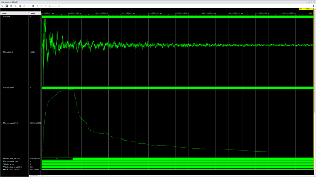
We are now ready to simulate our design. We use our handy SystemVerilog WAVE file reader to load a snare hit into our testbench, which also includes the conversion from fixed- to floating-point representation. The results of the simulation are shown in the figure below.
The upper analog waveform shows the incoming snare hit, while the lower one shows the calculated RMS value. We can see that the RMS measurement ‘lags’ behind the audio signal and reaches its maximum value much later. This lag can be controlled by adjusting the length of the averaging window, with a longer average introducing more lag. At about 20 ms the RMS values become more stable and then have a sharp decline for a short period before starting to decline more slowly. This correlates roughly with the time that our logic starts removing samples from the accumulator, since up until that point the circular buffer only contained zeroes (the data output of the circular buffer is the signal directly below the RMS bus).
In our next post we will introduce our first module for dynamic range processing of audio signals: the Clipper.
Cheers,
Isaac


