In this post we will go over the implementation of a floating-point audio clipper for our FPGA Audio Processor.
What is an Audio Clipper?
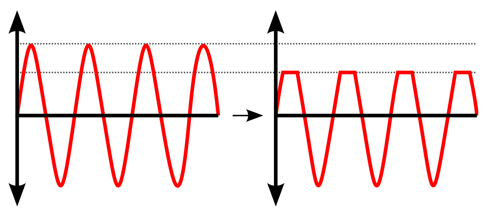
Clipping is a simple form of dynamic range processing. A clipper has a threshold against which it compares the incoming audio samples. If they exceed this threshold, the clipper sets the outgoing samples to a fixed value, usually the same as or very close to the threshold. If the incoming audio samples do not exceed the threshold, the clipper sends them unchanged to its output. The visual representation of this processing is shown in the figure below.
Why (and why not) use a Clipper
There are two common uses for a clipper: as an overflow protection device, and as a creative device. As an overflow protection device, the clipper is used as the last processing element in an audio processing pipeline, where it is guaranteed to keep every sample within the dynamic range of the DAC.
As a creative device, a clipper is often used for adding harmonics to the sound and increasing the perceived loudness of an audio track (those two phenomena go hand in hand). There are more subtle ways to add harmonic content to an audio signal, but a clipper definitely has its place. Furthermore, the harmonics introduced by intentionally clipping a signal can be more controllable and pleasant than simply allowing the samples to overflow.
In most cases however, a clipper is not meant to replace a compressor or a limiter. Those devices have more sophisticated ways of measuring the amplitude of the incoming signal and applying gain reduction in a less ‘aggressive’ manner. We will explore compressors and limiters later on.
Floating-Point Clipper in SystemVerilog
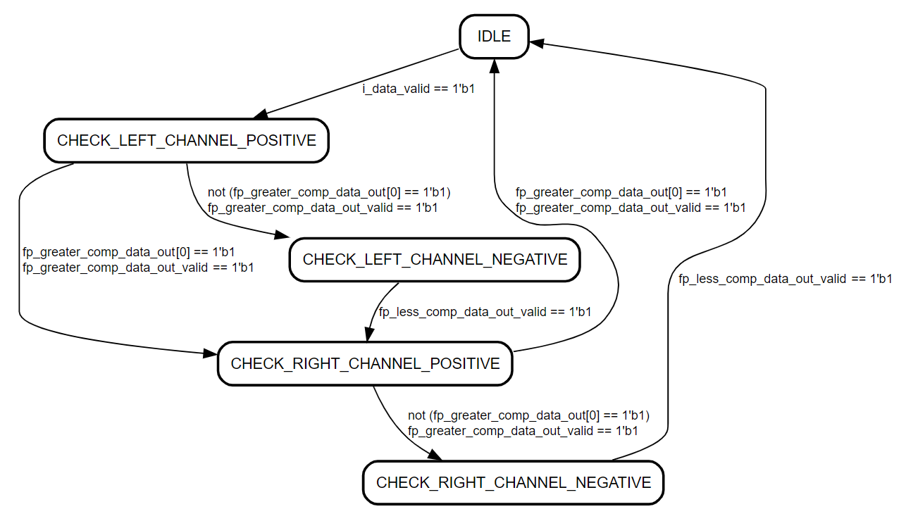
Our clipper uses floating-point greater-than and smaller-than comparators to decide when to manipulate the signal values. the logic goes as follows:
- Check if the sample is greater than the positive threshold. If it is, set it to the positive clipping value. If it is not, go to the next step.
- Check if the sample is smaller than the negative threshold. If it is, set it to the negative clipping value. If it is not, go to the next step.
- Send the audio sample to the output of the clipper without changing its value.
The figure below shows the state diagram for the Clipper FSM.
The complete code for the clipper module is shown below.
module clipper (
    input   logic               i_clock,
    // Audio Input
    input   logic               i_data_valid,
    input   logic   [31 : 0]    i_data_left,
    input   logic   [31 : 0]    i_data_right,
    // Audio Output
    output  logic               o_data_valid,
    output  logic   [31 : 0]    o_data_left,
    output  logic   [31 : 0]    o_data_right
);

    timeunit 1ns;
    timeprecision 1ps;

    logic           fp_greater_comp_data_in_valid;
    logic [31 : 0]  fp_greater_comp_data_a_in;
    logic           fp_greater_comp_data_out_valid;
    logic [7 : 0]   fp_greater_comp_data_out;
    fp_greater_equal_comp fp_greater_equal_comp_inst (
        .aclk                   (i_clock),
        .s_axis_a_tvalid        (fp_greater_comp_data_in_valid),
        .s_axis_a_tdata         (fp_greater_comp_data_a_in),
        .s_axis_b_tvalid        (fp_greater_comp_data_in_valid),
        .s_axis_b_tdata         (32'h4AF1ADF8),     // 7919356, ~-0.5 dBFS
        .m_axis_result_tvalid   (fp_greater_comp_data_out_valid),
        .m_axis_result_tdata    (fp_greater_comp_data_out)
    );

    logic           fp_less_comp_data_in_valid;
    logic [31 : 0]  fp_less_comp_data_a_in;
    logic           fp_less_comp_data_out_valid;
    logic [7 : 0]   fp_less_comp_data_out;
    fp_less_equal_comp fp_less_equal_comp_inst (
        .aclk                   (i_clock),
        .s_axis_a_tvalid        (fp_less_comp_data_in_valid),
        .s_axis_a_tdata         (fp_less_comp_data_a_in),
        .s_axis_b_tvalid        (fp_less_comp_data_in_valid),
        .s_axis_b_tdata         (32'hCAF1ADF8),     // -7919356, ~-0.5 dBFS
        .m_axis_result_tvalid   (fp_less_comp_data_out_valid),
        .m_axis_result_tdata    (fp_less_comp_data_out)
    );

    // Clipper FSM
    enum logic [2 : 0]  {IDLE,
                        CHECK_LEFT_CHANNEL_POSITIVE,
                        CHECK_LEFT_CHANNEL_NEGATIVE,
                        CHECK_RIGHT_CHANNEL_POSITIVE,
                        CHECK_RIGHT_CHANNEL_NEGATIVE} clipper_fsm_state = IDLE;
    logic [31 : 0] data_left = 'b0;
    logic [31 : 0] data_right = 'b0;

    always_ff @(posedge i_clock) begin : clipper_fsm
        case (clipper_fsm_state)
            IDLE : begin
                o_data_valid <= 1'b0;
                fp_greater_comp_data_in_valid <= 1'b0;
                fp_less_comp_data_in_valid <= 1'b0;
                if (i_data_valid == 1'b1) begin
                    data_left <= i_data_left;
                    data_right <= i_data_right;
                    fp_greater_comp_data_in_valid <= 1'b1;
                    fp_greater_comp_data_a_in <= i_data_left;
                    clipper_fsm_state <= CHECK_LEFT_CHANNEL_POSITIVE;
                end
            end

            CHECK_LEFT_CHANNEL_POSITIVE : begin
                fp_greater_comp_data_in_valid <= 1'b0;
                if (fp_greater_comp_data_out_valid == 1'b1) begin
                    if (fp_greater_comp_data_out[0] == 1'b1) begin
                        o_data_left <= 32'h4AF1ADFA;    // 7919357
                        fp_greater_comp_data_in_valid <= 1'b1;
                        fp_greater_comp_data_a_in <= data_right;
                        clipper_fsm_state <= CHECK_RIGHT_CHANNEL_POSITIVE;
                    end else begin
                        fp_less_comp_data_in_valid <= 1'b1;
                        fp_less_comp_data_a_in <= data_left;
                        clipper_fsm_state <= CHECK_LEFT_CHANNEL_NEGATIVE;
                    end
                end
            end

            CHECK_LEFT_CHANNEL_NEGATIVE : begin
                fp_less_comp_data_in_valid <= 1'b0;
                if (fp_less_comp_data_out_valid == 1'b1) begin
                    if (fp_less_comp_data_out[0] == 1'b1) begin
                        o_data_left <= 32'hCAF1ADFA;    // -7919357
                    end else begin
                        o_data_left <= data_left;
                    end
                    fp_greater_comp_data_in_valid <= 1'b1;
                    fp_greater_comp_data_a_in <= data_right;
                    clipper_fsm_state <= CHECK_RIGHT_CHANNEL_POSITIVE;
                end
            end

            CHECK_RIGHT_CHANNEL_POSITIVE : begin
                fp_greater_comp_data_in_valid <= 1'b0;
                if (fp_greater_comp_data_out_valid == 1'b1) begin
                    if (fp_greater_comp_data_out[0] == 1'b1) begin
                        o_data_right <= 32'h4AF1ADFA;    // 7919357
                        o_data_valid <= 1'b1;
                        clipper_fsm_state <= IDLE;
                    end else begin
                        fp_less_comp_data_in_valid <= 1'b1;
                        fp_less_comp_data_a_in <= data_right;
                        clipper_fsm_state <= CHECK_RIGHT_CHANNEL_NEGATIVE;
                    end
                end
            end

            CHECK_RIGHT_CHANNEL_NEGATIVE : begin
                fp_less_comp_data_in_valid <= 1'b0;
                if (fp_less_comp_data_out_valid == 1'b1) begin
                    if (fp_less_comp_data_out[0] == 1'b1) begin
                        o_data_right <= 32'hCAF1ADFA;    // -7919357
                    end else begin
                        o_data_right <= data_right;
                    end
                    o_data_valid <= 1'b1;
                    clipper_fsm_state <= IDLE;
                end
            end

            default : begin
                clipper_fsm_state <= IDLE;
            end
        endcase
    end
endmodule
Notice how we are comparing the incoming samples against +/-7919356, but clip them to +/-7919357. This guarantees that we will trigger the overflow alarm in our Stereo LED Meter each time we clip the signal.
Clipper Simulation
For the simulation of our clipper module, we will once again use our SystemVerilog WAVE file reader to load a snare hit and use it as an input. However, after converting the samples to floating-point format we multiply them by two to simulate the data values data would engage our clipper. The simulation waveform is shown in Figure 3 below.
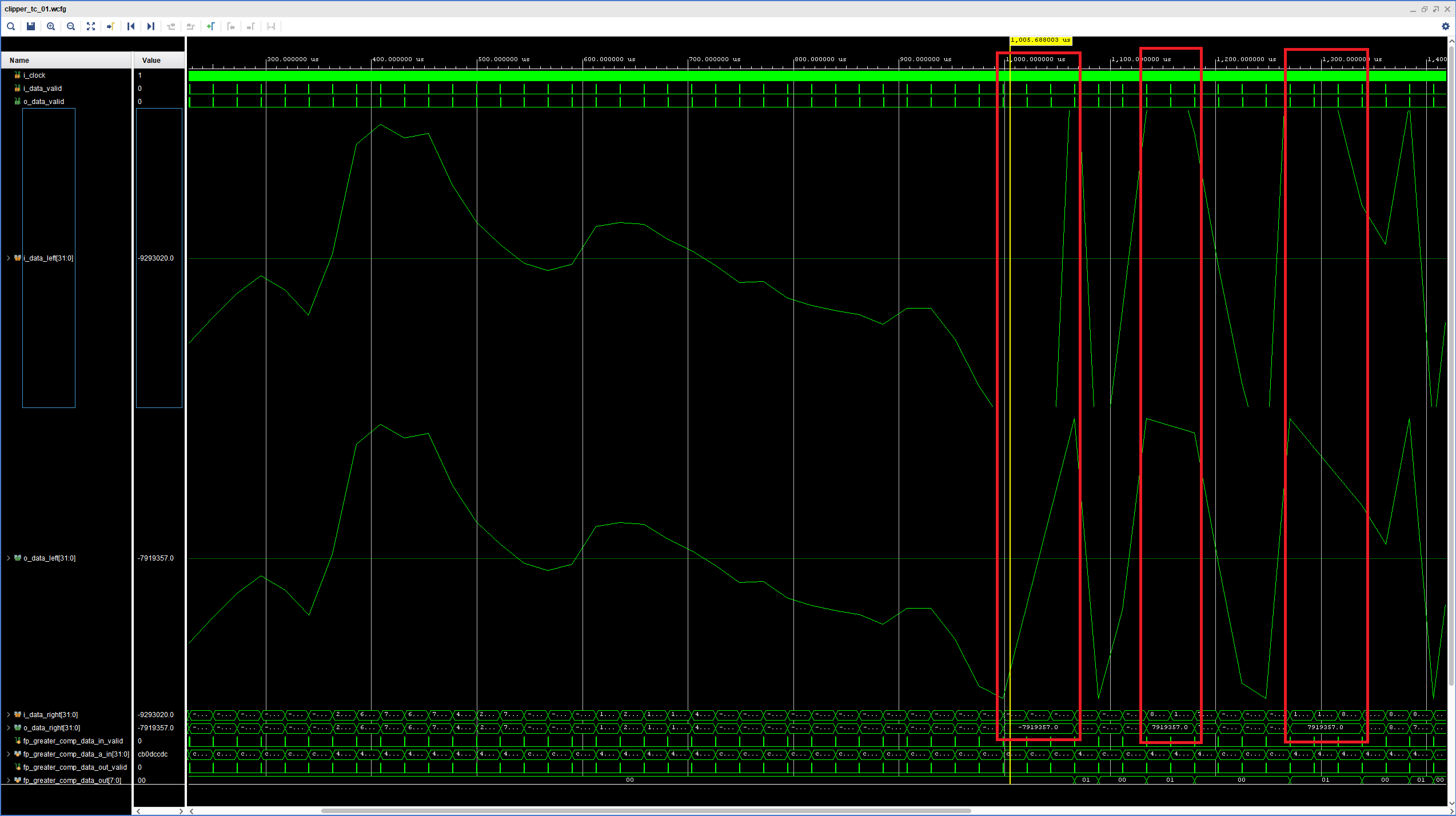
The upper analog waveform shows the left input signal, i.e. our snare hit with a 2x gain. The lower analog waveform shows the left output of the clipper. The display in both signals has been scaled to +/-8.388.607, the dynamic range of our audio codec. Before the 1 ms mark the input signal remained within the supported amplitude boundaries, but then we can see that its peak get larger than what could be represented with 24 bits (actually, we can’t see it, as it is out of the range of the display).
We can be absolutely certain that the clipper is being engaged by looking at the floating-point values below the output waveform, they show the right input and right output signals, from top to bottom. There we can see that, while the input keeps changing, the output remains at the +/-7.919.357 clipping value for several samples.
Clipping in Float- to Fixed-Point Conversion
While I was running the simulations for this module, I realized that, for our specific Audio Processor, a clipper might not be needed. Because we perform the float- to fixed-point conversion at the end of our audio-processing pipeline, any value outside of the range of the audio codec will be clipped by the float- to fixed-point converter.
So, did we just waste our time here? Not at all! Having a clipper with an adjustable threshold will always be valuable. On the one hand, we often want to set our clipping value to be somewhat lower than the maximum supported by our codec. And on the other hand, remember that a clipper is also a creative tool, so we must be able to set our threshold and clipping values to whatever we want. We might even use different threshold for each channel or clip the positive samples to a different absolute value than the negative samples.
In the next post we will improve our fixed- to floating- to fixed-point conversion as we introduce a new recurring series in the Blog. Stay tuned!
Cheers,
Isaac