In this post, the second part of our series exploring a floating-point FPGA audio equalizer, we will describe the logic of our double-precision floating-point Biquad and use it implement a low-pass filter.
Floating-Point Biquad Filter Architecture
As we discussed in the first part of this series, we will use the Direct Form II Transposed Structure of the Biquad Filter as the basis for our equalizer. This topology is shown in the figure below.
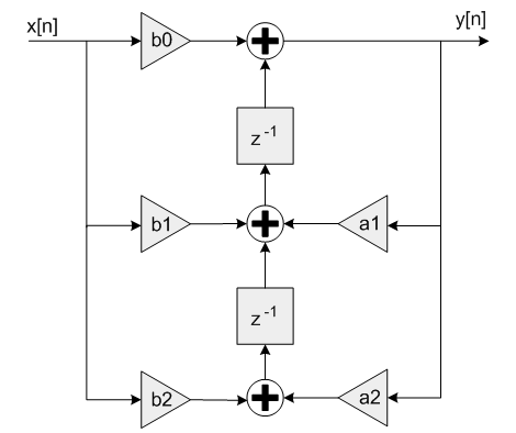
We will use two hierarchical levels: the Biquad Filter module will remain at the upper level, and will be responsible for managing the delayed samples and the coefficients used by the filter. The Biquad Equation module will be instantiated inside the Biquad Filter module and will be responsable for performing the calculations dictated by the filter’s transfer function.
The advantage of this two-level approach is twofold. First, by managing the delayed samples and coefficients independently from the calculation, we can more easily reuse the Biquad Equation logic for different channels. Second, this kind of separation will make it possible to change how the calculation is carried out (for instance when experimenting with different optimization goals or an HLS description) while keeping the rest of our design unchanged.
Biquad Filter
The logic in the Biquad Filter module is described in the Biquad Control FSM, which performs the following tasks:
- Update the delayed input samples each time a new sample arrives
- Trigger the processing of each channel and wait for it to be completed
- Update the delayed output samples when the calculation has been completed
The code for the Biquad Filter module is shown below.
module biquad_filter # (
    parameter integer DP_FLOATING_POINT_BIT_WIDTH = 64
    ) (
    input   logic                                       i_clock,
    // Audio Input
    input   logic                                       i_data_valid,
    input   logic   [DP_FLOATING_POINT_BIT_WIDTH-1 : 0] i_data_left,
    input   logic   [DP_FLOATING_POINT_BIT_WIDTH-1 : 0] i_data_right,
    // Audio Output
    output  logic                                       o_data_valid,
    output  logic   [DP_FLOATING_POINT_BIT_WIDTH-1 : 0] o_data_left,
    output  logic   [DP_FLOATING_POINT_BIT_WIDTH-1 : 0] o_data_right
);

    timeunit 1ns;
    timeprecision 1ps;

    // Biquad equation: y[n] = a0 * x[n] + d1
    //                  d1 = a1 * x[n-1] + b1 * y[n-1] + d2
    //                  d2 = a2 * x[n-2] + b2 * y[n-2]

    // Filter coefficients (lowpass, 44.1 kHz, 500 Hz Fc, 0.7071 Q, 6 dB Gain)
    logic [DP_FLOATING_POINT_BIT_WIDTH-1 : 0] a0 = 64'h3F53C838DB03A294;    // a0 = 0.0012074046354035072
    logic [DP_FLOATING_POINT_BIT_WIDTH-1 : 0] a1 = 64'h3F63C838DB03A294;    // a1 = 0.0024148092708070144
    logic [DP_FLOATING_POINT_BIT_WIDTH-1 : 0] a2 = 64'h3F53C838DB03A294;    // a2 = 0.0012074046354035072
    logic [DP_FLOATING_POINT_BIT_WIDTH-1 : 0] b1 = 64'h3FFE63AA866C6F75;    // b1 = 1.8993325472756315
    logic [DP_FLOATING_POINT_BIT_WIDTH-1 : 0] b2 = 64'hBFECEEE57E8EE62E;    // b2 = -0.9041621658172454

    // Biquad Equation
    logic biquad_equation_start;
    logic [DP_FLOATING_POINT_BIT_WIDTH-1 : 0]   xn_left   = 'b0;
    logic [DP_FLOATING_POINT_BIT_WIDTH-1 : 0]   xn_1_left = 'b0;
    logic [DP_FLOATING_POINT_BIT_WIDTH-1 : 0]   xn_2_left = 'b0;
    logic [DP_FLOATING_POINT_BIT_WIDTH-1 : 0]   yn_left   = 'b0;
    logic [DP_FLOATING_POINT_BIT_WIDTH-1 : 0]   yn_1_left = 'b0;
    logic [DP_FLOATING_POINT_BIT_WIDTH-1 : 0]   yn_2_left = 'b0;
    logic [DP_FLOATING_POINT_BIT_WIDTH-1 : 0]   xn_right = 'b0;
    logic [DP_FLOATING_POINT_BIT_WIDTH-1 : 0]   xn_1_right = 'b0;
    logic [DP_FLOATING_POINT_BIT_WIDTH-1 : 0]   xn_2_right = 'b0;
    logic [DP_FLOATING_POINT_BIT_WIDTH-1 : 0]   yn_right = 'b0;
    logic [DP_FLOATING_POINT_BIT_WIDTH-1 : 0]   yn_1_right = 'b0;
    logic [DP_FLOATING_POINT_BIT_WIDTH-1 : 0]   yn_2_right = 'b0;
    logic [DP_FLOATING_POINT_BIT_WIDTH-1 : 0]   biquad_equation_xn;
    logic [DP_FLOATING_POINT_BIT_WIDTH-1 : 0]   biquad_equation_xn_1;
    logic [DP_FLOATING_POINT_BIT_WIDTH-1 : 0]   biquad_equation_xn_2;
    logic [DP_FLOATING_POINT_BIT_WIDTH-1 : 0]   biquad_equation_yn_1;
    logic [DP_FLOATING_POINT_BIT_WIDTH-1 : 0]   biquad_equation_yn_2;
    logic                                       biquad_equation_done;
    logic [DP_FLOATING_POINT_BIT_WIDTH-1 : 0]   biquad_equation_yn;
    biquad_equation # (
      .DP_FLOATING_POINT_BIT_WIDTH (DP_FLOATING_POINT_BIT_WIDTH)
    ) biquad_equation_inst (
      .i_clock  (i_clock),
      .i_start  (biquad_equation_start),
      .i_a0     (a0),
      .i_a1     (a1),
      .i_a2     (a2),
      .i_b1     (b1),
      .i_b2     (b2),
      .i_xn     (biquad_equation_xn),
      .i_xn_1   (biquad_equation_xn_1),
      .i_xn_2   (biquad_equation_xn_2),
      .i_yn_1   (biquad_equation_yn_1),
      .i_yn_2   (biquad_equation_yn_2),
      .o_done   (biquad_equation_done),
      .o_yn     (biquad_equation_yn)
    );

    // Biquad Control FSM
    enum logic [2 : 0]  {IDLE,
                        PROCESS_LEFT_CHANNEL,
                        UPDATE_LEFT_SAMPLES,
                        PROCESS_RIGHT_CHANNEL,
                        UPDATE_RIGHT_SAMPLES} biquad_control_fsm_state = IDLE;

    always_ff @(posedge i_clock) begin : biquad_control_fsm
        case (biquad_control_fsm_state)
            IDLE : begin
                biquad_equation_start <= 1'b0;
                o_data_valid <= 1'b0;
                if (i_data_valid == 1'b1) begin
                    xn_2_left <= xn_1_left;
                    xn_1_left <= xn_left;
                    xn_left <= i_data_left;
                    xn_2_right <= xn_1_right;
                    xn_1_right <= xn_right;
                    xn_right <= i_data_right;
                    biquad_control_fsm_state <= PROCESS_LEFT_CHANNEL;
                end
            end

            PROCESS_LEFT_CHANNEL : begin
                biquad_equation_xn <= xn_left;
                biquad_equation_xn_1 <= xn_1_left;
                biquad_equation_xn_2 <= xn_2_left;
                biquad_equation_yn_1 <= yn_left;
                biquad_equation_yn_2 <= yn_1_left;
                biquad_equation_start <= 1'b1;
                biquad_control_fsm_state <= UPDATE_LEFT_SAMPLES;
            end

            UPDATE_LEFT_SAMPLES : begin
                biquad_equation_start <= 1'b0;
                if (biquad_equation_done == 1'b1) begin
                    yn_2_left <= yn_1_left;
                    yn_1_left <= yn_left;
                    yn_left <= biquad_equation_yn;
                    biquad_control_fsm_state <= PROCESS_RIGHT_CHANNEL;
                end
            end

            PROCESS_RIGHT_CHANNEL : begin
                biquad_equation_xn <= xn_right;
                biquad_equation_xn_1 <= xn_1_right;
                biquad_equation_xn_2 <= xn_2_right;
                biquad_equation_yn_1 <= yn_right;
                biquad_equation_yn_2 <= yn_1_right;
                biquad_equation_start <= 1'b1;
                biquad_control_fsm_state <= UPDATE_RIGHT_SAMPLES;
            end

            UPDATE_RIGHT_SAMPLES : begin
                biquad_equation_start <= 1'b0;
                if (biquad_equation_done == 1'b1) begin
                    yn_2_right <= yn_1_right;
                    yn_1_right <= yn_right;
                    yn_right <= biquad_equation_yn;
                    o_data_valid <= 1'b1;
                    biquad_control_fsm_state <= IDLE;
                end
            end

            default : begin
                biquad_control_fsm_state <= IDLE;
            end
        endcase
    end

    assign o_data_left = yn_left;
    assign o_data_right = yn_right;

endmodule
One thing to note about the coefficients Biquad Filter module: they were calculated using this tool in the Ear Level Engineering website, which is based on their description of the Direct Form II Transposed Structure. However, the formula that we use is taken from the CMSIS-DSP library, and in order to use the coefficients from the Ear Level Engineering calculator, we must invert the sign of the coefficients used on the delayed outputs (b1, b2). If we don’t, our filter will become unstable and its output will grow infinitely.
Biquad Equation
The Biquad Equation module performs the actual calculation of the Biquad Filter output. As mentioned before, we use the Direct Form II Transposed Structure, whose transfer function is described by the CMSIS-DSP library as follows:
y[n] = b0 * x[n] + d1, where:
d1 = b1 * x[n-1] + a1 * y[n-1] + d2
d2 = b2 * x[n-2] + a2 * y[n-2]
The Biquad Equation module takes all the inputs required for the transfer function (delayed input samples, delayed out samples, coefficients) and calculates the corresponding output sample. To achieve this, we instantiate double-precision floating-point adder and multiplier IP cores and then design a state machine that triggers each operation contained in the transfer function until we have calculated our desired output. The code for the Biquad Equation module is shown below.
module biquad_equation # (
    parameter integer DP_FLOATING_POINT_BIT_WIDTH = 64
    ) (
    input   logic                                       i_clock,
    input   logic                                       i_start,
    // Coefficients
    input   logic   [DP_FLOATING_POINT_BIT_WIDTH-1 : 0] i_a0,
    input   logic   [DP_FLOATING_POINT_BIT_WIDTH-1 : 0] i_a1,
    input   logic   [DP_FLOATING_POINT_BIT_WIDTH-1 : 0] i_a2,
    input   logic   [DP_FLOATING_POINT_BIT_WIDTH-1 : 0] i_b1,
    input   logic   [DP_FLOATING_POINT_BIT_WIDTH-1 : 0] i_b2,
    // Samples
    input   logic   [DP_FLOATING_POINT_BIT_WIDTH-1 : 0] i_xn,
    input   logic   [DP_FLOATING_POINT_BIT_WIDTH-1 : 0] i_xn_1,
    input   logic   [DP_FLOATING_POINT_BIT_WIDTH-1 : 0] i_xn_2,
    input   logic   [DP_FLOATING_POINT_BIT_WIDTH-1 : 0] i_yn_1,
    input   logic   [DP_FLOATING_POINT_BIT_WIDTH-1 : 0] i_yn_2,
    // Audio Output
    output  logic                                       o_done,
    output  logic   [DP_FLOATING_POINT_BIT_WIDTH-1 : 0] o_yn
);

    timeunit 1ns;
    timeprecision 1ps;

    // Biquad equation: y[n] = a0 * x[n] + d1
    //                  d1 = a1 * x[n-1] + b1 * y[n-1] + d2
    //                  d2 = a2 * x[n-2] + b2 * y[n-2]

    logic                                       adder_data_in_valid;
    logic [DP_FLOATING_POINT_BIT_WIDTH-1 : 0]   adder_data_in_a;
    logic [DP_FLOATING_POINT_BIT_WIDTH-1 : 0]   adder_data_in_b;
    logic                                       adder_result_valid;
    logic [DP_FLOATING_POINT_BIT_WIDTH-1 : 0]   adder_result;
    dp_fp_adder dp_fp_adder_inst (
        .aclk                   (i_clock),
        .s_axis_a_tvalid        (adder_data_in_valid),
        .s_axis_a_tdata         (adder_data_in_a),
        .s_axis_b_tvalid        (adder_data_in_valid),
        .s_axis_b_tdata         (adder_data_in_b),
        .m_axis_result_tvalid   (adder_result_valid),
        .m_axis_result_tdata    (adder_result)
    );

    logic                                       mult_data_in_valid;
    logic [DP_FLOATING_POINT_BIT_WIDTH-1 : 0]   mult_data_in_a;
    logic [DP_FLOATING_POINT_BIT_WIDTH-1 : 0]   mult_data_in_b;
    logic                                       mult_result_valid;
    logic [DP_FLOATING_POINT_BIT_WIDTH-1 : 0]   mult_result;
    dp_fp_multiplier dp_fp_multiplier_inst (
        .aclk                   (i_clock),
        .s_axis_a_tvalid        (mult_data_in_valid),
        .s_axis_a_tdata         (mult_data_in_a),
        .s_axis_b_tvalid        (mult_data_in_valid),
        .s_axis_b_tdata         (mult_data_in_b),
        .m_axis_result_tvalid   (mult_result_valid),
        .m_axis_result_tdata    (mult_result)
        );

        // Biquad Equation FSM
    logic [DP_FLOATING_POINT_BIT_WIDTH-1 : 0]   aux;
    enum logic [3 : 0]  {IDLE,
                        MULT_A2_XN2,
                        MULT_B2_YN2,
                        ADD_D2,
                        MULT_A1_XN1,
                        ADD_D1_AUX,
                        MULT_B1_YN1,
                        ADD_D1,
                        MULT_A0_XN,
                        ADD_YN} biquad_equation_fsm_state = IDLE;
    always_ff @(posedge i_clock) begin : biquad_equation_fsm
        case (biquad_equation_fsm_state)
            IDLE : begin
                o_done <= 1'b0;
                adder_data_in_valid <= 1'b0;
                mult_data_in_valid <= 1'b0;
                if (i_start == 1'b1) begin
                    mult_data_in_a <= i_a2;
                    mult_data_in_b <= i_xn_2;
                    mult_data_in_valid <= 1'b1;
                    biquad_equation_fsm_state <= MULT_A2_XN2;
                end
            end

            MULT_A2_XN2 : begin
                mult_data_in_valid <= 1'b0;
                if (mult_result_valid == 1'b1) begin
                    aux <= mult_result;
                    mult_data_in_a <= i_b2;
                    mult_data_in_b <= i_yn_2;
                    mult_data_in_valid <= 1'b1;
                    biquad_equation_fsm_state <= MULT_B2_YN2;
                end
            end

            MULT_B2_YN2 : begin
                mult_data_in_valid <= 1'b0;
                if (mult_result_valid == 1'b1) begin
                    adder_data_in_a <= mult_result;
                    adder_data_in_b <= aux;
                    adder_data_in_valid <= 1'b1;
                    biquad_equation_fsm_state <= ADD_D2;
                end
            end

            ADD_D2 : begin
                adder_data_in_valid <= 1'b0;
                if (adder_result_valid == 1'b1) begin
                    aux <= adder_result;                // aux holds d2
                    mult_data_in_a <= i_a1;
                    mult_data_in_b <= i_xn_1;
                    mult_data_in_valid <= 1'b1;
                    biquad_equation_fsm_state <= MULT_A1_XN1;
                end
            end

            MULT_A1_XN1 : begin
                mult_data_in_valid <= 1'b0;
                if (mult_result_valid == 1'b1) begin
                    adder_data_in_a <= mult_result;
                    adder_data_in_b <= aux;
                    adder_data_in_valid <= 1'b1;
                    biquad_equation_fsm_state <= ADD_D1_AUX;
                end
            end

            ADD_D1_AUX : begin
                adder_data_in_valid <= 1'b0;
                if (adder_result_valid == 1'b1) begin
                    aux <= adder_result;
                    mult_data_in_a <= i_b1;
                    mult_data_in_b <= i_yn_1;
                    mult_data_in_valid <= 1'b1;
                    biquad_equation_fsm_state <= MULT_B1_YN1;
                end
            end

            MULT_B1_YN1 : begin
                mult_data_in_valid <= 1'b0;
                if (mult_result_valid == 1'b1) begin
                    adder_data_in_a <= mult_result;
                    adder_data_in_b <= aux;
                    adder_data_in_valid <= 1'b1;
                    biquad_equation_fsm_state <= ADD_D1;
                end
            end

            ADD_D1 : begin
                adder_data_in_valid <= 1'b0;
                if (adder_result_valid == 1'b1) begin
                    aux <= adder_result;                // aux holds d1
                    mult_data_in_a <= i_a0;
                    mult_data_in_b <= i_xn;
                    mult_data_in_valid <= 1'b1;
                    biquad_equation_fsm_state <= MULT_A0_XN;
                end
            end

            MULT_A0_XN : begin
                mult_data_in_valid <= 1'b0;
                if (mult_result_valid == 1'b1) begin
                    adder_data_in_a <= mult_result;
                    adder_data_in_b <= aux;
                    adder_data_in_valid <= 1'b1;
                    biquad_equation_fsm_state <= ADD_YN;
                end
            end

            ADD_YN : begin
                adder_data_in_valid <= 1'b0;
                if (adder_result_valid == 1'b1) begin
                    o_done <= 1'b1;
                    o_yn <= adder_result;
                    biquad_equation_fsm_state <= IDLE;
                end
            end

            default : begin
                biquad_equation_fsm_state <= IDLE;
            end
        endcase
    end

endmodule
Simulation and Implementation Results
We are now ready to test our equalizer. We use the testbench introduced in the first part of this series to make sure our design works as expected. We are aiming for a low-pass filter with 500 Hz Fc, 6 dB Gain and a Q factor of 0.7071 for our 44.1 kHz sample rate. The result of the simulation with our mono snare hit test file is shown in the figure below.
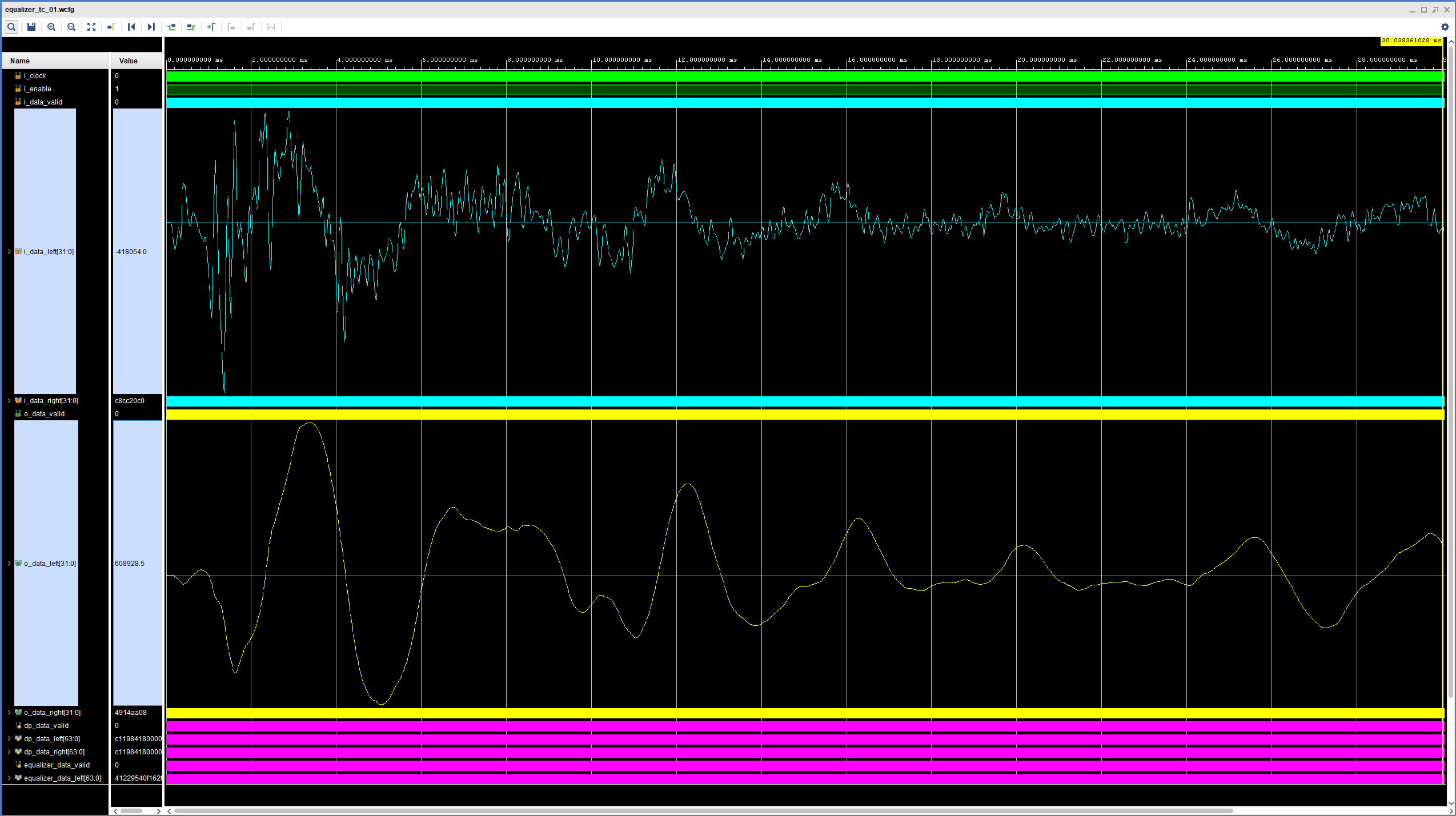
An exhaustive analysis of the performance of this filter is well outside the scope of this post, so we’ll accept the visual representation of the waveforms as the first evidence that the filters does what we designed it to do. The high-frequency components of the snare hit are smoothed out and we are left with the low-frequency content that we would expect to see after applying a low-pass filter. A much better (and more satisfying) test is to program the FPGA and use the ZedBoard’s SW1 to enable/disable the low-pass filter in real time while playing some of your favorite music.
The figure below shows the resource utilization of our Biquad Filter. We can see that the double-precision floating-point multiplier consumes 11 DSP slices out of the 18 used by the entire design so far. This increased resource utilization is one of the major disadvantages of floating-point processing with FPGAs, especially in double precision. There might also be potential for reducing resource utilization by managing intermediate signals more efficiently, but that was not a priority for this design.

Another way in which the cost of floating-point processing manifests itself is the latency and throughput of the system. Our Biquad Filter has a latency of around 3.1299 us, which given our current 44.100 Hz sample rate would allow us to process six channels of audio. While this is acceptable for the stereo processing in which we have focused so far, it is good to keep in mind the ways in which it could be improved. These are roughly in the order that I would approach them in a real project:
- The Biquad Equation FSM is a very straightforward, ‘naive’ implementation, in which only one addition or one multiplication takes place at a time. While there are some dependencies between these operands, the overall performance can almost certainly be increased by a more thoughtful design of this control logic.
- Both the control logic and the floating-point cores currently run at 100 MHz. This can probably be more than doubled while still achieving timing closure.
- Adjusting the floating-point core’s Latency, Rate and Cycles per Operation parameters might yield a better compromise between performance and resource utilization than what we have seen here.
- Multiple instances of the Biquad Equation module will linearly increase the performance of the system (as well as its resource utilization).
In the next part of this series we will replace our Biquad Filter logic with an HLS-generated IP core. See you then!
Cheers,
Isaac
The RTL and simulation files for this post are available in the FPGA Audio Processor repository under this tag.