In this post, the final of a three-part series exploring an FPGA audio Equalizer based on a Biquad Filter, we will do a quick HLS implementation of our Biquad Equation module and compare its resource utilization and performance to our RTL description.
What have we done so far?
We started this series by setting our goal to implement an audio equalizer based on a Biquad Filter. We also set up the single- to double-precision floating-point conversion, as well as the general architecture of the equalizer and the simulation environment. In the second installment we focused on describing the core RTL logic of the equalizer after defining two hierarchical levels: a Biquad Filter module and a Biquad Equation module, which we then simulated and tested on the ZedBoard. In this post we will explore an alternative description with Vitis HLS, compare it to our current RTL solution and see how we can improve the performance of our implementation.
HLS Description
In a previous series we explored the workflow for generating an RTL module from a C++ description and used the exported IP core for the linear-to-dBFS Conversion in our Audio Processor. This time we will replace the RTL-based Biquad Equation module, which uses double-precision floating-point IP cores for addition and multiplication, with a C++ description using doubles.
Because we set up the Biquad Equation module to receive all the inputs and calculate the outputs, the C++ description of our module is fairly simple, it only contains the biquad equation itself. The C++ header file with the function declaration and the source file with the function definition are shown below.
#ifndef __BIQUAD_EQUATION_HLS_HPP__
#define __BIQUAD_EQUATION_HLS_HPP__

double biquad_equation_hls( double i_a0,
                            double i_a1,
                            double i_a2,
                            double i_b1,
                            double i_b2,
                            double i_xn,
                            double i_xn_1,
                            double i_xn_2,
                            double i_yn_1,
                            double i_yn_2);

#endif
#include "biquad_equation_hls.hpp"
double biquad_equation_hls( double i_a0,
double i_a1,
double i_a2,
double i_b1,
double i_b2,
double i_xn,
double i_xn_1,
double i_xn_2,
double i_yn_1,
double i_yn_2) {
double o_yn;
o_yn = i_a0 * i_xn + i_a1 * i_xn_1 + i_a2 * i_xn_2 + i_b1 * i_yn_1 + i_b2 * i_yn_2;
return o_yn;
}Given the simplicity of this function, we will skip the testbench and simulation part of the HLS workflow this time.
The figure below shows the results of the Vitis HLS C Synthesis.
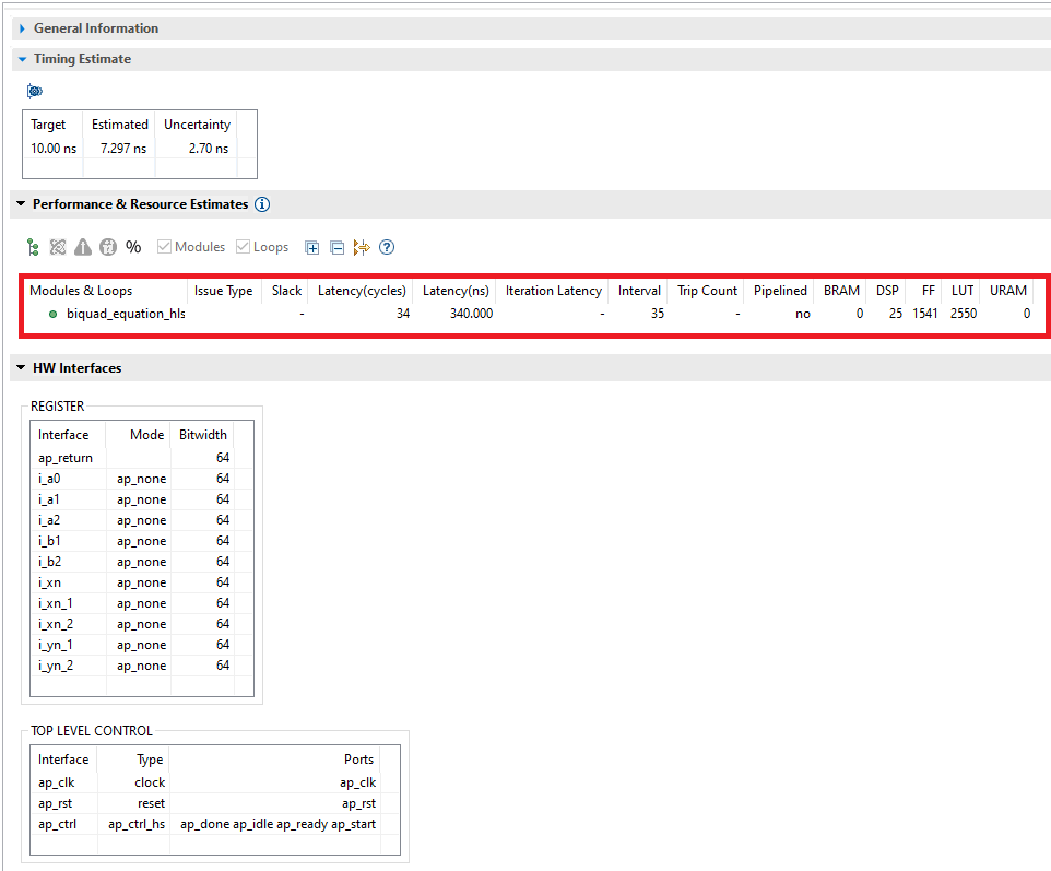
The first thing to notice is that the latency of the HLS solution (34 cycles) is quite a bit lower than the latency of our RTL description (79 cycles). Also, the DSP utilization of the HLS solution (25 DSP Slices) is almost twice as high as that of our description (14 DSP Slices). We will come back to this later.
The figure below shows the resource utilization of the Biquad Equation module generated by Vitis HLS after the design has been placed and routed.
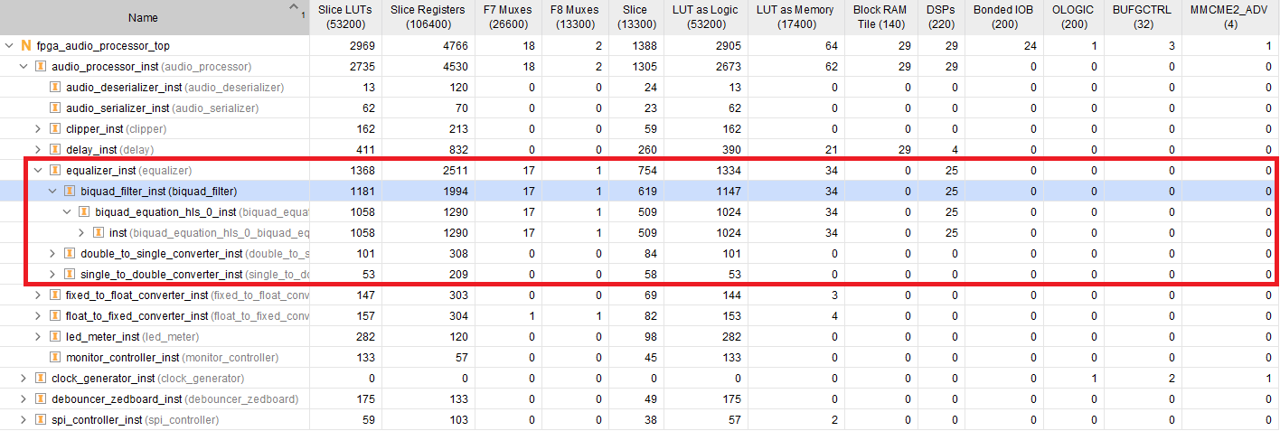
These results are somewhat unexpected. While the Vitis HLS solution has significantly lower latency than ours, it uses more than twice the number of DSP slices. The LUT and register utilization is different than the Vitis HLS estimates: 1058 LUTs in Vivado vs 2550 in Vitis HLS, and 1994 Registers in Vivado vs 1541 in Vitis HLS. I also experimented with explicitely describing the operator precedence with parenthesis, but all variations of that resulted in a significantly higher utilization of DSP Slices reported by Vitis HLS after C Synthesis. Other than these observations, simulating and testing the HLS-generated core on the hardware worked as expected.
Floating-Point IP Core Optimizations
We will update our solution so that the latency performance is comparable to the HLS solution. Though there is potential for optimizing the Biquad Equation FSM, the current latency is dominated by the performance of the floating-point adder and multiplier cores. One floating-point addition requires 14 clock cycles, a multiplication 16. Because the biquad equation contains five multiplications and one addition, processing one channel with our fully sequential approach requires at least 136 cycles, and that’s before taking account any overhead in our control FSM.
The most straightforward way to reduce the latency of the Biquad Equation module is by reducing the latency setting of the floating-point adder and multiplier modules. After the most demanding configurations of one and two cycles failed to immediately meet timing, I settled for a three-cycle latency for each core. For a total of 9 operations, the latency is reduced to 27 cycles, plus the FSM overhead (10 cycles). The figure below shows the resource utilization of the Biquad Equation module with reduced latency after the design has been placed and routed.
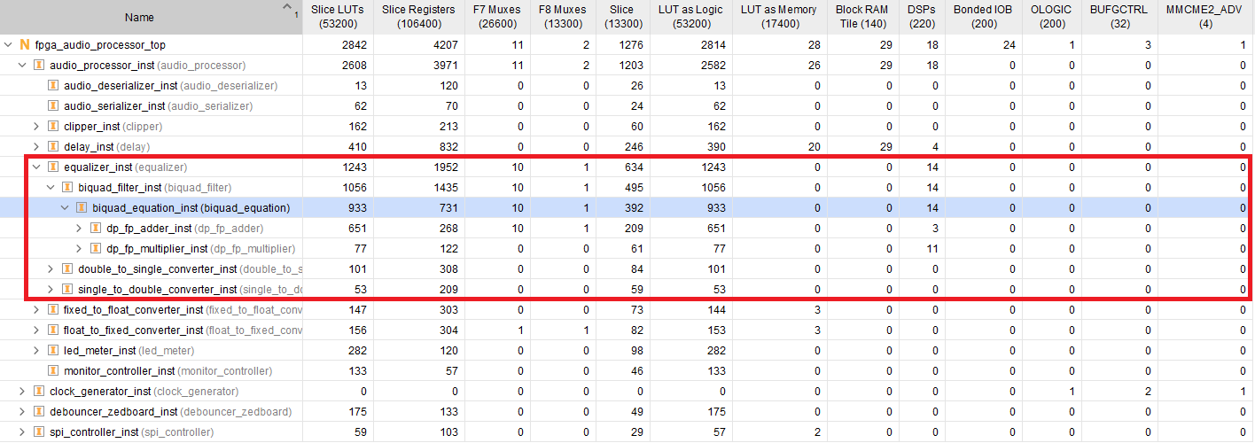
Our optimized design utilizes less than half the amount of DSP slices, as well as fewer LUTs and registers. Because we ‘only’ require 3 additional cycles to complete the operation, I’ll consider this a worthwhile trade-off. The HLS description was definitely quicker than our SystemVerilog FSM, but then again, the FSM was simple enough that the development time shouldn’t be the deciding factor. However, if we decided to try out other FSM architectures, HLS would most likely allow an easier and quicker design exploration.
Though this is by no means not an exhaustive analysis of Vitis HLS (we will explore that in detail later in the Blog) I still think this was an interesting experiment. I was surprised to see that the HLS-generated core used as many resources as it did. Sure, we didn’t do any design exploration with directives, which perhaps would improve the overall performance of the solution, but on the other hand, the RTL description is very straightforward and has potential for optimizations. Given how simple the transfer function is, I was expecting to see better results from Vitis HLS right out of the box. Perhaps I’ll revisit this topic in the future.
That’s it for this series. In the next post we will turn our attention to the simulation workflows using the the Vivado simulator.
Cheers,
Isaac
The RTL and simulation files for this post are available in the FPGA Audio Processor repository under this tag.