In this post, the first of a two-part series, we will explore how to set up and run an RTL simulation in Vivado that is separate from the synthesis and implementation flow.
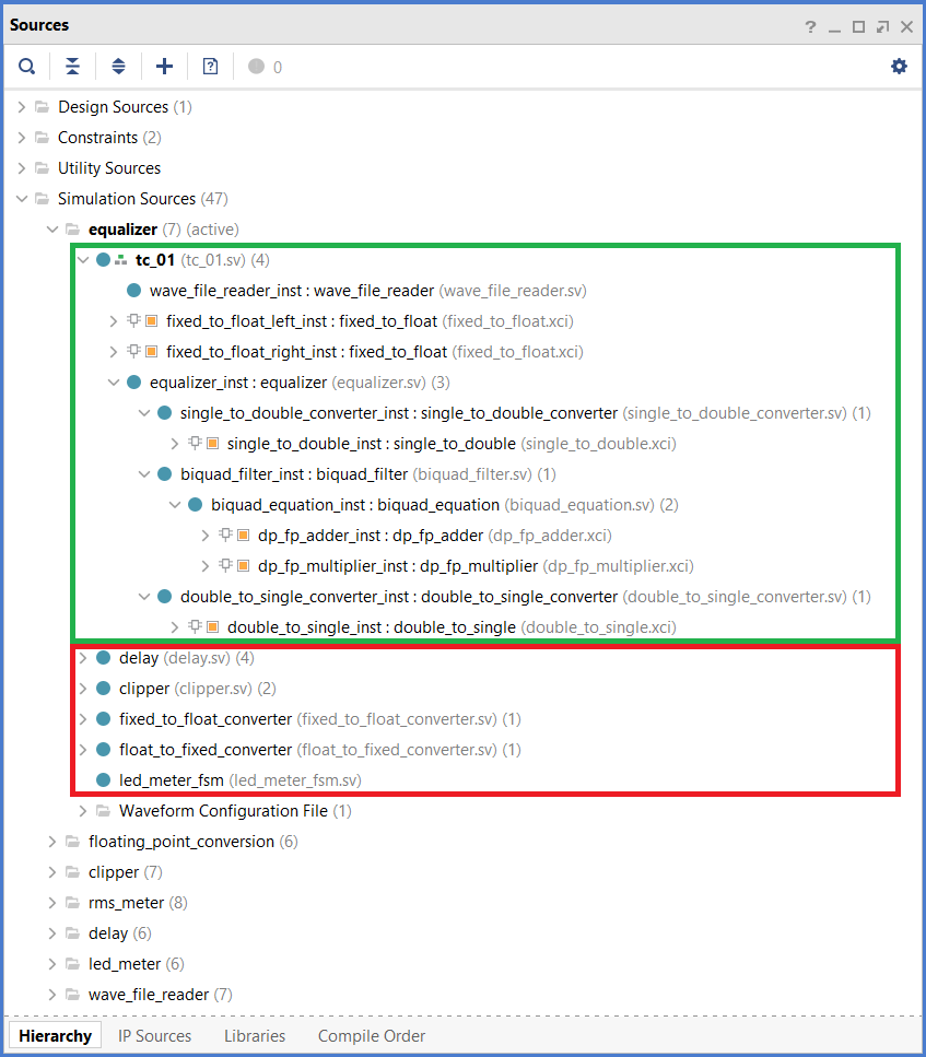
Our FPGA Audio Processor project includes module-level simulations for most of the components. Until now each of those simulations has been isolated by creating multiple simulation file sets, as shown in the figure below.
There are two main things that we could improve in this setup. First, we can see that each simulation file set includes the top-level testcase description (tc_01) at the highest hierarchy level, and all the instances are sprawled underneath it as one would expect (green box). However, we also see that all other design files, which are not part of that simulation, are also shown in the file set (red box). This is because by default all design sources are added to all simulation file sets, regardless of whether they are used in that particular simulation. Several attempts at getting only the relevant design files to show up in each simulation file set, including manually editing the Vivado project file, did not work reliably.
While having design files show up in the ‘wrong‘ simulation file set could be dismissed as a purely aesthetic inconvenience (not that I think that aesthetics are unimportant), a more consequential improvement would be to separate the simulation workflow from the synthesis and implementation workflow. Though Vivado includes the tools for simulation and synthesis/implementation in a single environment, most FPGA development tools do not, so it is a good idea to think of them as separate processes. I also find it subjectively better to only load the tools that we need for the task at hand, while the rest remains out of sight and out of mind.
Behavioral Simulation Workflow
Running a simulation in Vivado requires three steps (from UG900 v2021.2 Vivado Design Suite User Guide: Logic Simulation):
- Identifying and parsing design files
- Elaborating and generating an executable simulation snapshot of the design
- Running the simulation using the executable snapshot
These steps are performed regardless of whether we are simulating a standalone design or working within a project. When simulating a standalone design, we need to explicitely go through these steps every time. Not using a project also means that we are responsible for keeping the simulation files updated and recompiling them whenever they change.
There is one command for each of the steps described above:
- Identifying and parsing design files -> xvlog/xvhdl
- Elaborating and generating an executable simulation snapshot of the design -> xelab
- Running the simulation using the executable snapshot -> xsim
Strictly speaking these are not Vivado commands, but separate executable programs that are installed as part of the Vivado design suite. Let’s see how we can use them to simulate a simple RTL design.
Simulating RTL Sources
We will simulate our LED Meter module, which consists of a purely RTL description. The current version of the LED Meter is described in this post, and we will use our SytemVerilog WAVE file reader as described here. To use the new, modular version of the SystemVerilog WAVE file reader we needed to update the LED Meter Testbench, whose new version is shown below.
module led_meter_tc_01();

    timeunit 1ns;
    timeprecision 1ps;

    logic clock;
    initial begin
        clock = 1'b0;
        forever begin
            #5ns;
            clock = ~clock;
        end
    end

    // WAVE File Reader
    logic           file_data_valid;
    logic [23 : 0]  file_data_left;
    logic [23 : 0]  file_data_right;
    wave_file_reader wave_file_reader_inst (
        .i_clock        (clock),
        .o_data_valid   (file_data_valid),
        .o_data_left    (file_data_left),
        .o_data_right   (file_data_right)
    );

    // LED Meter DUT
    logic [7 : 0]   led;
    led_meter led_meter_inst (
        .i_clock        (clock),
        // Audio Input
        .i_data_left    (file_data_left),
        .i_data_right   (file_data_right),
        .i_data_valid   (file_data_valid),
        // LED Meter Output
        .o_led          (led)
    );

endmodule
Now we get to the fun part. Instead of creating a Vivado project, we will run the simulation from an OS terminal. For that we will use two scripts, we’ll call them ‘sim.tcl‘ and ‘xsim.tcl‘. Let’s start with ‘sim.tcl‘, which is shown below.
exec xvlog -sv      ../../../hdl/led_meter_fsm.sv
exec xvlog -sv      ../../../hdl/led_meter.sv
exec xvlog -sv      ../../common/wave_file_reader.sv
exec xvlog -sv      ./led_meter_tc_01.sv
exec xelab          led_meter_tc_01 -s led_meter_tc_01_sim -debug typical
exec xsim           led_meter_tc_01_sim -t xsim.tcl
start_gui
open_wave_database  led_meter_tc_01_sim.wdb
In lines 1 through 4 we execute the ‘xvlog‘ command with the -sv option to parse our SystemVerilog RTL and testbench files. Since there are no VHDL sources in this design, we won’t use the ‘xvhdl‘ command.
In line 5 we execute ‘xelab’ on the top-level module of our design (led_meter_tc_01) to create the simulation snapshot (led_meter_tc_01_sim). By setting the debug switch to ‘typical‘ we ensure that we can log signals to a waveform file.
In line 6 we execute ‘xsim‘ on the simulation snapshot generated in the previous step. By using the ‘-t‘ option we can pass an additional script to ‘xsim’ to control how the simulation will be run. We’ll come back to this in a moment.
In line 7 we start the GUI so we can visualize the logged signals, and in line 8 we open the waveform database that to which we logged the signals during the simulation. Because the waveform configuration file has the same name as the waveform database, Vivado loads the configuration automtically. Otherwise we would need to load it explicitely using the ‘open_wave_config‘ command. Notice how these last two commands don’t have the word ‘exec‘ at the beginning: this is because they are actual Vivado Tcl commands. As we mentioned earlier, ‘xvlog‘, ‘xelab‘ and ‘xsim‘ are standalone executable programs installed in our PC, and the ‘exec‘ command allows us to call other programs from a Tcl console.
Let’s return to line 6, where we run ‘xsim‘ and pass it an additional Tcl script, ‘xsim.tcl‘, which is shown below.
log_wave [get_objects /led_meter_tc_01/led_meter_inst/*]
run -all
exit
In line 1 we tell the simulator to log all the signals of the ‘led_meter_inst‘ module. In line 2 we run the simulation until our testbench finishes. In line 3 we return control to the Tcl console from which ‘xsim‘ was called.
To run the simulation we open an OS terminal in the simulation directory and run the following command:
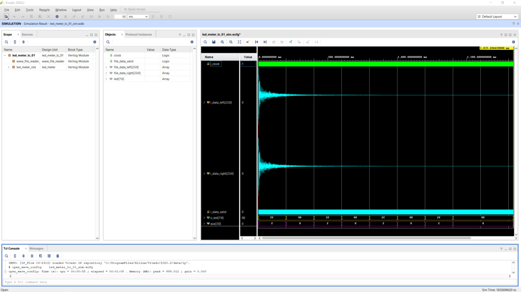
vivado -mode batch -source sim.tclThis command opens Vivado in batch mode and passes it our simulation script. The figure below shows the results of the standalone simulation of the LED Meter.
And that’s it, we now simulated a simple, but nontrivial RTL design in Vivado without having to create a project. In the next post we will explore how to simulate a design that includes packaged IP cores in addition to RTL sources. Stay tuned!
Cheers,
Isaac
The RTL and simulation files for this post are available in the FPGA Audio Processor repository under this tag.


