In this post, the last of a three-part series exploring dynamic range control of audio signals using a limiter, we add lookahead support to our Floating-Point FPGA Limiter module.
In the first part of this series we created a first RTL description of a floating-point limiter for our FPGA Audio Processor and verified its functionality in simulation. In the second part we added support for stereo processing and evaluated the results by listening to some a limited audio clip.
Lookahead
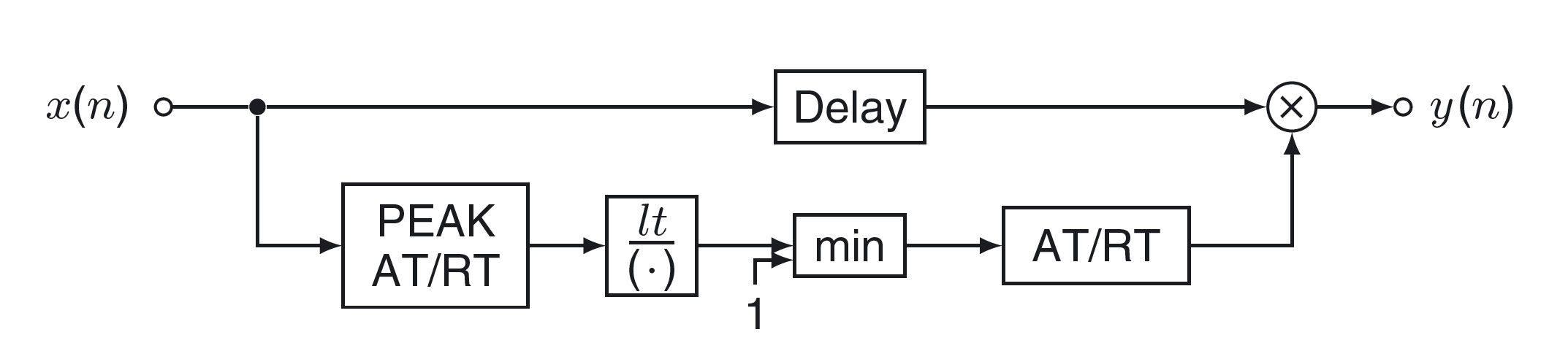
The figure below shows the structure of the limiter that we are developing. By now we have implemented the lower path of the block diagram. Now we are ready to add support for the upper ‘Delay’ path, which also known in the audio world as ‘lookahead‘.
The gain reduction of our Limiter works by comparing the filtered envelope of the incoming audio signal with a threshold value. Once the filtered envelope goes above the threshold, a gain smaller than unity is applied to reduce the dynamic range of the outgoing signal. When the filtered envelope goes back below the threshold, the gain is incremented until it reaches unity.
Depending on the attack and release times set for the envelope detection and gain reduction, it is possible that samples above the threshold get to the output of the limiter. The lookahead aims to minimize the probability of this happening by calculating the amount of gain reduction to be applied to the output in advance, that is, by looking ahead to the next few input samples before generating the output. This way if the limiter knows that the input will exceed the threshold, say, 10 samples from the current time, it can apply a higher gain reduction to the current sample. This has the added benefit that the gain reduction can be less drastic when using lookahead, which reduces the amount of higher-level harmonics on the output signal.
In a real-time implementation there is no way for the limiter logic to know the value of the samples that have not yet arrived at the input, so the lookahead is implemented by delaying the input samples before starting to calculate the outputs. Note that only the generation of the output is delayed, the calculation of the limiter gain is done as each sample arrives.
RTL Description
We need to make two changes to the Limiter FSM module to add lookahead support. The first change is to add a FIFO that will store the incoming audio samples, effectively implementing the ‘Delay‘ element of the block diagram in Figure 1. For this I chose a distributed RAM implementation with a depth of 64 words, which provides up to 1.45 ms of lookahead at 44.1 kHz. We connect the ‘data_in’ and ‘write_enable’ inputs of the FIFO directly to the data and data valid inputs of the Limiter FSM module.
The Xilinx FIFO IP core supports first word fall-through and word count, which are not strictly necessary, but will allow us to add the lookahead logic with minimal changes to the FSM.
The second change is to update our logic so that the gain is calculated for each input, but the output is only generated after the desired number of samples have been delayed. We can achieve this by updating the last two states of our FSM, as shown in the code below.
always_ff @(posedge i_clock) begin
    case (limiter_fsm_state)

    (...)

    CALC_OUTPUT : begin
        fp_adder_valid_in <= 1'b0;
        if (fp_adder_valid_out == 1'b1) begin
            gain <= fp_adder_data_out;
            if (lookahead_fifo_data_count > LOOKAHEAD_SAMPLE_COUNT) begin
                lookahead_fifo_rd_en <= 1'b1;
                fp_mult_valid_in <= 1'b1;
                fp_mult_data_in_a <= fp_adder_data_out;
                fp_mult_data_in_b <= lookahead_fifo_data_out;
                limiter_fsm_state <= DRIVE_OUTPUT;
            end else begin
                limiter_fsm_state <= WAIT_SAMPLE;
            end
        end
    end

    DRIVE_OUTPUT : begin
        lookahead_fifo_rd_en <= 1'b0;
        fp_mult_valid_in <= 1'b0;
        if (fp_mult_valid_out == 1'b1) begin
            o_data_valid <= 1'b1;
            o_data <= fp_mult_data_out;
            limiter_fsm_state <= WAIT_SAMPLE;
        end
    end

    default : begin
        limiter_fsm_state <= IDLE;
    end
endcase
Simulation
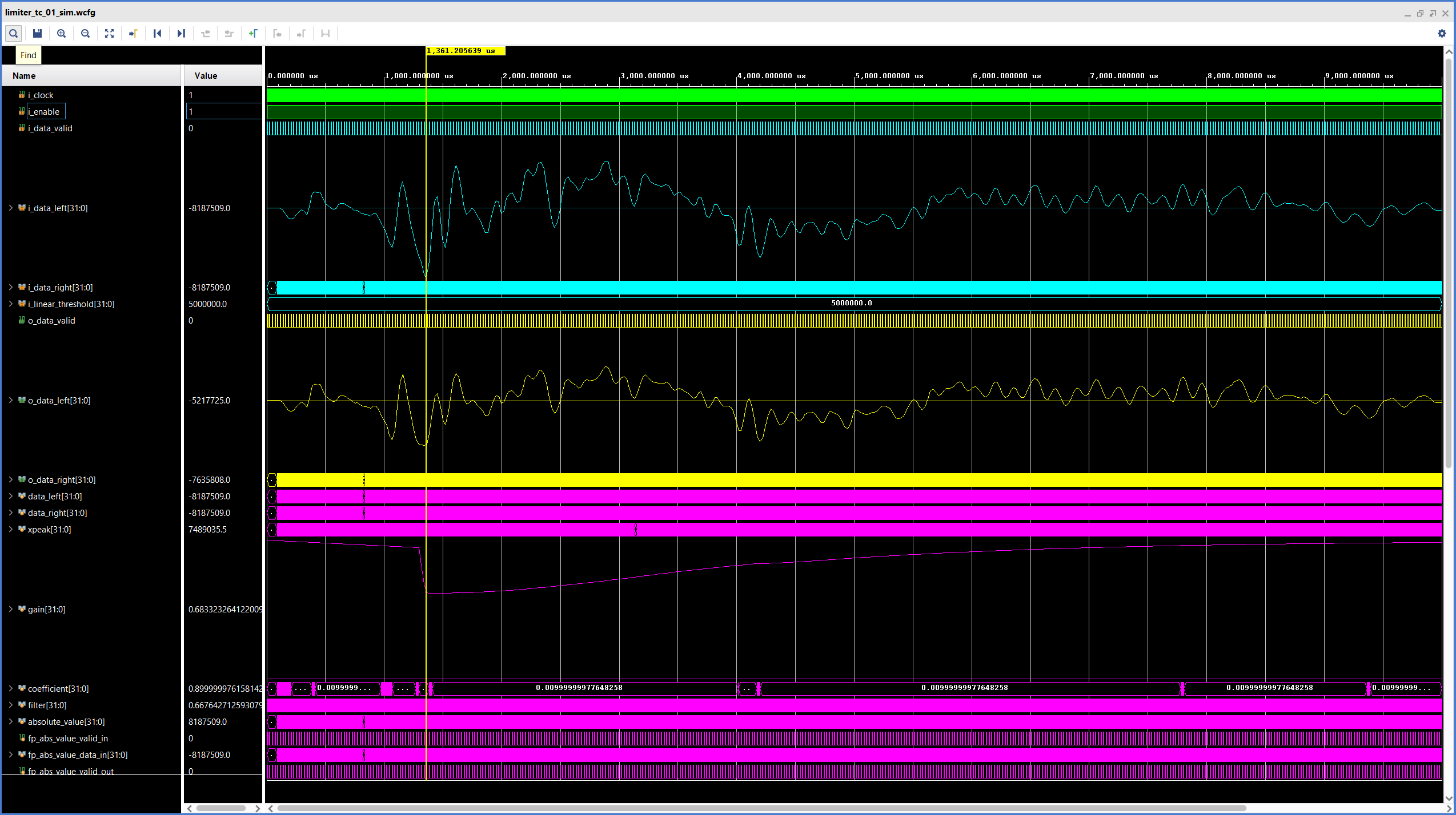
We don’t have to make any changes to the testbench itself, so the simulation could run as-is. However, we will update the simulation scripts and the waveform configuration file to plot the internal signals of the Limiter FSM module. The results of the simulation are shown in the figure below.
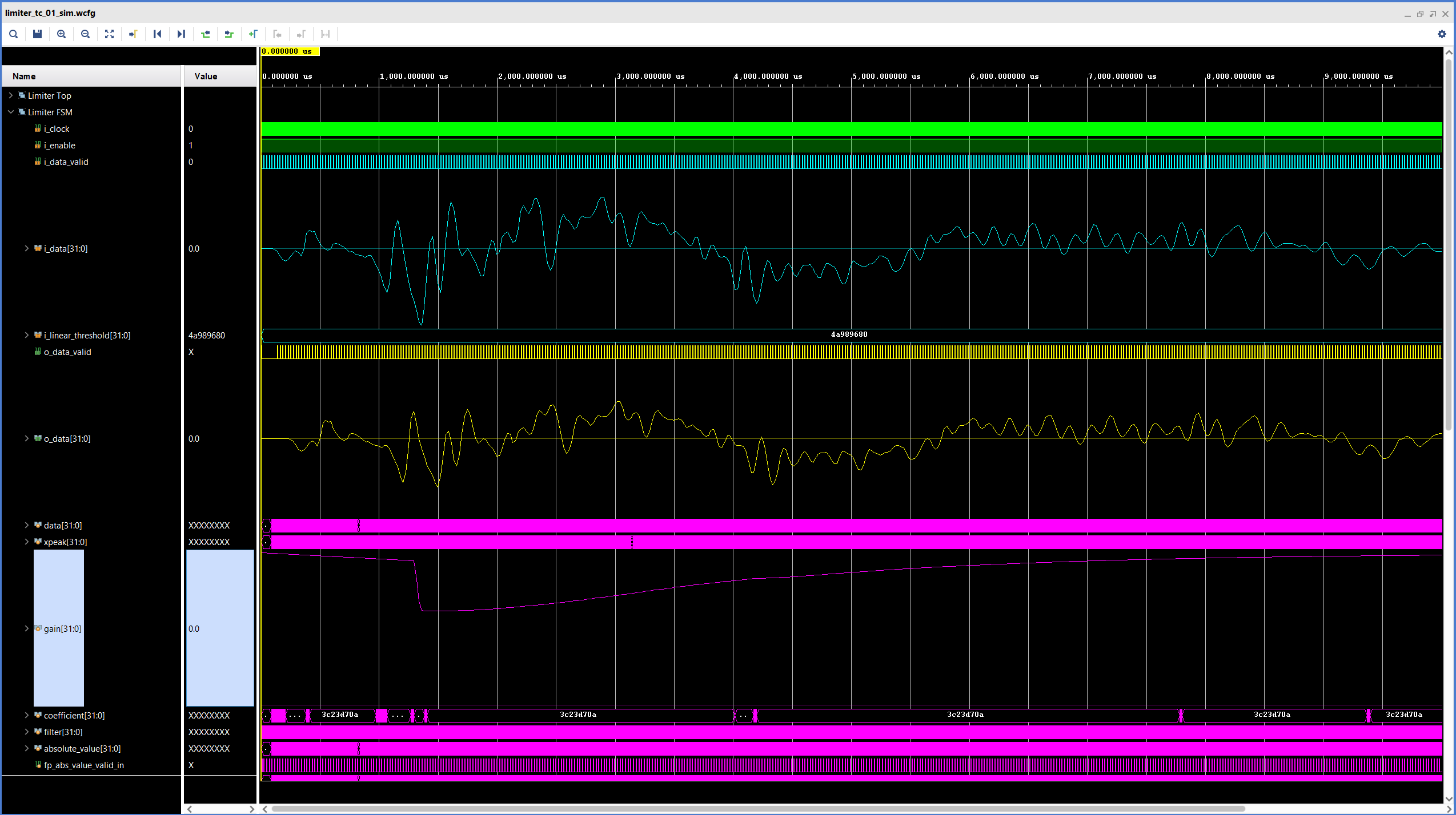
The waveform shows how the output signal is delayed with respect to the input. For comparison, the figure below shows the waveform corresponding to the first version of the Limiter module, without lookahead.
Since we are using a relatively short lookahead value, the difference is not dramatic, but still clearly visible. The same gain adjustment takes place in both cases, but when using lookahead the gain is applied earlier.
As mentioned before, the lookahead function is often used to minimize the chance of samples above the threshold getting through to the output of the limiter, or to apply a gentler gain reduction that introduces fewer harmonics. However, we must keep in mind that these behaviors are dependent on both the input signal and the attack and release times of the limiter (which, in turn may be different for the envelope detection and for the gain adjustment). For our current input signal and limiter settings, a too long lookahead would cause the gain reduction to start recovering before the inputs with the highest absolute values are processed. In this scenario the lookahead would actually make it more likely that input signals above the threshold will get through to the output of the limiter.
And that’s it for our exploration of dynamic range control with a limiter. As always, I hope you find this part of the project useful and encourage you to experiment with it. We#ll be back next week with a maintenance update to our FPGA Audio Processor in another installment of the Paying Off Technical Debt series. See you then!
Cheers,
Isaac
All files for this post are available in the FPGA Audio Processor repository under this tag.