In this post we will convert the convert the pure RTL description of our FPGA Audio Processor into a Block Design to be used with the Vivado IP Integrator.
Up until now our FPGA Audio Processor design has been entirely RTL-based. I wanted to start it off this way to focus on the processing made in the programmable logic, without bringing in the overhead of a processor core and its associated software into play. Though this approach has served us well so far, it has a major limitation: runtime configurability and user interaction. Using buttons and switches allows us to do some basic configuration, but for anything even remotely sophisticated, software running on an on-chip processor is a must.
In Vivado, if we want to use a processor core, we need to instantiate it in a Block Design in the IP Integrator. We will do that in a later post, right now we will create a Block Design without a processor core, we will add our RTL modules to the Block Design and double-check that everything works as it did with pure RTL.
RTL Modules in the Vivado IP Integrator
There are two ways to add logic elements to a Block Design: packaged IP and RTL modules. While packaging IP is great for distribution once we are done developing our logic, adding RTL modules is a very convenient way to incorporate logic to a Block Design during development.
To add RTL modules to a Block Design we can right-click on the canvas and select ‘Add Module…‘, which will show a list of the modules that can be added to the block design. As of version 2021.1 the Vivado IP Integrator only supports VHDL and Verilog RTL Modules, so we need to write Verilog wrappers for each component whose top module we would like to make visible in the Block Design. This is a tedious task, but not an overly complicated one. Hopefully SystemVerilog support for RTL Modules will be added soon.
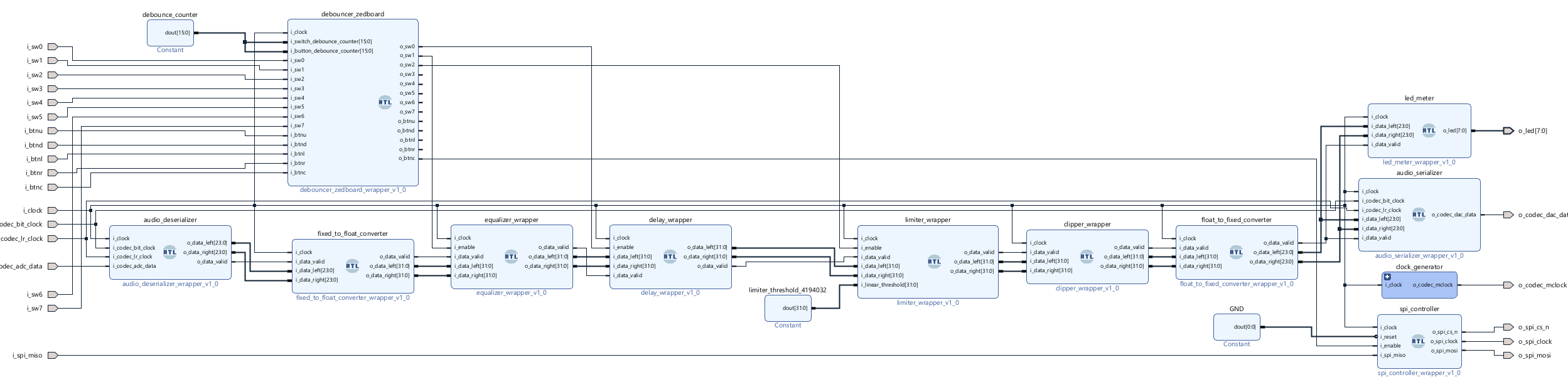
The figure below shows our FPGA Audio Processor Block Design once all modules have been added. Here we have left out the Audio Processor hierarchical level, which is no longer needed. Also missing is the Monitor Controller, which I’ve decided to leave out because I barely used it, and my audio interface has its own monitor controller section. The Clock Wizard and ODDR components were added as IP from within the Block Design.
One thing to keep in mind when adding RTL Modules to a Block Design is that, if the RTL Modules instantiate IP (which is the case for many of our modules), the IP cannot remain as a standalone out-of-context (OOC) synthesis run. Vivado lets us know that with the following error:
ERROR: [filemgmt 56-328] Reference \’delay_wrapper\’ contains sub-design file \’C:/rtlaudiolab/fpga_audio_processor/ip/delay_circular_buffer/delay_circular_buffer.xci\’, which is configured for out-of-context synthesis. OOC sub-designs are not allowed in the reference. To change the setting, use TCL command: \’set_property generate_synth_checkpoint 0 [get_files delay_circular_buffer.xci]\’
Fortunately the solution is embedded in the error message. For each IP instantiated within the RTL modules that we would like to add to the Block Design, we run the following command:
set_property generate_synth_checkpoint 0 [get_files delay_circular_buffer.xci]This will remove the OOC synthesis setting and remove the IP run. To remove the IP run for the Clock Wizard and ODDR elements we can run the following commands:
delete_ip_run [get_files -of_objects [get_fileset clk_wiz_0]]
delete_ip_run [get_files -of_objects [get_fileset oddr_0]]
One final change that I had to make was increasing the latency of the double-precision floating point multiplier in the Equalizer to four cycles, since the design was not meeting timing.
After validating the Block Design and selecting it as the top-level element of our project, we are ready to generate the bitstream and check that everything works on the board.
Vivado Version Upgrade
In addition to switching from traditional RTL logic to a block design, two changes were made this week to the FPGA Audio Processor design. The first change was to update the project to the latest version of Vivado, 2021.2.
The upgrade process was fairly straight forward:
- Opening the project in the new version of Vivado and agreeing to do the upgrade
- Running ‘Reports -> Report IP Status’ and letting the tool upgrade all the obsolete IP
- Upgrading the corresponding IP libraries in the standalone simulation scripts
SystemVerilog WAVE File Reader Fix
The second change has to do with the audio file used as input for the SystemVerilog WAVE File Reader that we use for simulation. A reader pointed out in the comments that the Limiter simulation in Blog 029 was not working properly. After some debugging, he found out that it was due to an absolute path in the SystemVerilog WAVE File Reader pointing to the input audio file. I now added the path to the audio file as a module parameter which defaults to a relative path to the snare sample. Thanks John!
Cheers,
Isaac
All files for this post are available in the FPGA Audio Processor repository under this tag.