In this post, the first of a two-part series, we will implement and simulate an RTL floating-point FIR filter for our FPGA Audio Processor.
In a previous series we explored the IIR Biquad Filter as a foundational block for audio equalizers by implementing, simulating and testing a biquad-based low-pass filter our audio processor. Now we will turn our attention to FIR filtering and will implement a similar low-pass filter which we can then compare to the IIR version.
FIR Filters
A Finite Impulse Response (FIR) filter is a filter type whose outputs are only dependent on its inputs and its internal filter coefficients. The impulse response of a FIR filter will always reach zero (hence the ‘finite‘ naming). This contrasts with Infinite Impulse Response (IIR) filters, whose outputs also depend on past output values (in addition to the input and filter coefficients). The impulse response of an IIR filter theoretically never reaches zero (hence the ‘infinite’ naming), though in practice it becomes so small that it cannot be represented in any practical numeric system, so it is eventually approximated to zero.
The figure below shows the structure of a Direct Form FIR filter.
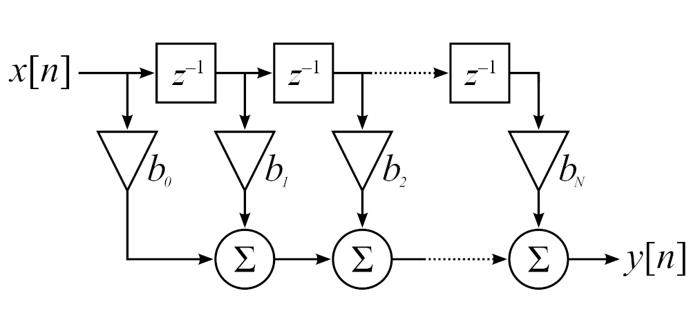
The Direct Form is obtained from the mathematical description of the FIR filter, the convolution operation. To calculate each filter output from a real-time audio stream we proceed as follows:
- Buffer as many input samples as filter coefficients
- Multiply each sample by its corresponding coefficient
- Add all the products together
Due to the initial buffering, there will be a delay between the arrival of the first input sample and the generation of the first output. Each time a new sample arrives it is added to the buffer, and the oldest sample is removed from the buffer. The three-step computation described above is then repeated.
FIR Filter Implementation in SystemVerilog
Our SystemVerilog FIR filter module will perform all the tasks required by the FIR filter computation described above. To do that it requires, in addition to our custom logic, three IP cores:
- a ROM memory, in which the filter coefficients are stored,
- a RAM memory, which serves as the buffer for the input samples, and
- a floating-point multiply-add module
The ROM memory is the most straightforward of the cores, with only a clock input, an address input, and a data output. The coefficients are written in a COEF file, and the file location is set when the IP is customized.
The RAM memory is used as a circular buffer, as we discussed in the implementation of our RMS meter. The depth of the DRAM must match the number of coefficients stored in the ROM. Because our filter requires a relatively low amount of taps, both the RAM and ROM are implemented as distributed memories.
As mentioned earlier, the core arithmetic operation of a FIR filter is the convolution, where each sample is multiplied by a coefficient, and all the products are then added together to generate the output. This operation, known as ‘multiply-accumulate’ or ‘multiply-add‘, is essential to DSP, and Xilinx’s Floating Core Operator IP includes a mode that performs a multiply-add as a single instruction.
The FIR Filter FSM drives the memory and multiply-add cores to provide the complete functionality of the FIR Filter. Upon start, it first waits for the sample DRAM to be filled. After that, for every news sample it cycles through the sample DRAM and coefficient DROM performing the multiply-add operations. When this is done, the FIR FIlter FSM updates the module outputs.
The RTL code for the FIR Filter module is shown below.
module fir_filter # (
    parameter integer SP_FLOATING_POINT_BIT_WIDTH = 32
    ) (
    input   logic                                       i_clock,
    // Audio Input
    input   logic                                       i_data_valid,
    input   logic   [SP_FLOATING_POINT_BIT_WIDTH-1 : 0] i_data_left,
    input   logic   [SP_FLOATING_POINT_BIT_WIDTH-1 : 0] i_data_right,
    // Audio Output
    output  logic                                       o_data_valid,
    output  logic   [SP_FLOATING_POINT_BIT_WIDTH-1 : 0] o_data_left,
    output  logic   [SP_FLOATING_POINT_BIT_WIDTH-1 : 0] o_data_right
);

    timeunit 1ns;
    timeprecision 1ps;

    logic [4 : 0]   sample_dram_wr_addr;
    logic [4 : 0]   sample_dram_rd_addr;
    logic [31 : 0]  sample_dram_data_out;
    fir_filter_sample_dram fir_filter_sample_dram_inst (
        .a          (sample_dram_wr_addr),
        .d          (i_data_left),
        .dpra       (sample_dram_rd_addr),
        .clk        (i_clock),
        .we         (i_data_valid),
        .qdpo       (sample_dram_data_out)
    );

    logic [4 : 0]   coeff_drom_rd_addr;
    logic [31 : 0]  coeff_drom_data_out;
    fir_filter_coeff_drom fir_filter_coeff_drom_inst (
        .a          (coeff_drom_rd_addr),
        .clk        (i_clock),
        .qspo       (coeff_drom_data_out)
    );

    logic                                       fp_mult_add_data_in_valid;
    logic [SP_FLOATING_POINT_BIT_WIDTH-1 : 0]   fp_mult_add_data_in_a;
    logic [SP_FLOATING_POINT_BIT_WIDTH-1 : 0]   fp_mult_add_data_in_b;
    logic [SP_FLOATING_POINT_BIT_WIDTH-1 : 0]   fp_mult_add_data_in_c;
    logic                                       fp_mult_add_data_out_valid;
    logic [SP_FLOATING_POINT_BIT_WIDTH-1 : 0]   fp_mult_add_data_out;
    fp_mult_add fp_mult_add_inst (
        .aclk                   (i_clock),
        .s_axis_a_tvalid        (fp_mult_add_data_in_valid),
        .s_axis_a_tdata         (fp_mult_add_data_in_a),
        .s_axis_b_tvalid        (fp_mult_add_data_in_valid),
        .s_axis_b_tdata         (fp_mult_add_data_in_b),
        .s_axis_c_tvalid        (fp_mult_add_data_in_valid),
        .s_axis_c_tdata         (fp_mult_add_data_in_c),
        .m_axis_result_tvalid   (fp_mult_add_data_out_valid),
        .m_axis_result_tdata    (fp_mult_add_data_out)
    );

    // FIR Filter FSM
    typedef enum logic [2 : 0]  {IDLE,
                                WAIT_SAMPLE,
                                START_MAC,
                                WAIT_FOR_MAC,
                                UPDATE_OUTPUT} fir_filter_fsm_t;
    fir_filter_fsm_t fir_filter_fsm_state = IDLE;
    logic [4 : 0] mac_counter;
    logic sample_buffer_full;
    logic mac_busy;
    logic [SP_FLOATING_POINT_BIT_WIDTH-1 : 0] accumulator;

    always_ff @(posedge i_clock) begin : fir_filter_fsm
        case (fir_filter_fsm_state)

            IDLE : begin
                fp_mult_add_data_in_a <= 32'd0;
                fp_mult_add_data_in_b <= 32'd0;
                fp_mult_add_data_in_c <= 32'd0;
                fp_mult_add_data_in_valid <= 1'b1;
                sample_dram_wr_addr <= 5'd0;
                sample_dram_rd_addr <= 5'b0;
                coeff_drom_rd_addr <= 5'b0;
                mac_counter <= 5'd0;
                sample_buffer_full <= 1'b0;
                mac_busy <= 1'b0;
                o_data_valid <= 1'b0;
                o_data_left <= 32'd0;
                o_data_right <= 32'd0;
                fir_filter_fsm_state <= WAIT_SAMPLE;
            end

            WAIT_SAMPLE : begin
                o_data_valid <= 1'b0;
                fp_mult_add_data_in_valid <= 1'b0;
                if (sample_buffer_full == 1'b0) begin
                    if (i_data_valid == 1'b1) begin
                        sample_dram_wr_addr <= sample_dram_wr_addr + 1;
                        mac_counter <=  mac_counter + 1;
                    end
                    if (mac_counter == 5'd30) begin
                        sample_buffer_full <= 1'b1;
                    end
                end else begin
                    if (i_data_valid == 1'b1) begin
                        sample_dram_wr_addr <= sample_dram_wr_addr + 1;
                        sample_dram_rd_addr <= sample_dram_wr_addr + 1;
                        coeff_drom_rd_addr <= 5'd0;
                        mac_counter <= 5'd0;
                        fir_filter_fsm_state <= START_MAC;
                    end
                end
            end

            START_MAC : begin
                if (mac_counter == 5'd30) begin
                    mac_counter <= 5'd0;
                    fir_filter_fsm_state <= UPDATE_OUTPUT;
                end else begin
                    fp_mult_add_data_in_valid <= 1'b1;
                    fp_mult_add_data_in_a <= sample_dram_data_out;
                    fp_mult_add_data_in_b <= coeff_drom_data_out;
                    fp_mult_add_data_in_c <= accumulator;
                    fir_filter_fsm_state <= WAIT_FOR_MAC;
                end
            end

            WAIT_FOR_MAC : begin
                fp_mult_add_data_in_valid <= 1'b0;
                if (fp_mult_add_data_out_valid == 1'b1) begin
                    mac_counter <= mac_counter + 1;
                    accumulator <= fp_mult_add_data_out;
                    sample_dram_rd_addr <= sample_dram_rd_addr + 1;
                    coeff_drom_rd_addr <= coeff_drom_rd_addr + 1;
                    fir_filter_fsm_state <= START_MAC;
                end
            end

            UPDATE_OUTPUT : begin
                accumulator <= 32'd0;
                o_data_valid <= 1'b1;
                o_data_left <= accumulator;
                fir_filter_fsm_state <= WAIT_SAMPLE;
            end

            default : begin
                fir_filter_fsm_state <= IDLE;
            end
        endcase
    end

endmodule
FIR Filter Coefficients
Now that we have a working convolution engine, we need to figure out which coefficients we must use. The coefficients determine the type of filtering that we will apply to our incoming signal.
When designing a filter, we should start by defining the filter characteristics as well as possible. The most important (and obvious) will be filter type (high pass, low pass, etc.), cutoff frequency and attenuation. Other important, though less obvious characteristics include filter topology, acceptable ripple (both in the passband and stopband) and phase response. We can then enter the desired filter characteristics in a tool that will generate a list of coefficients to load into our ROM.
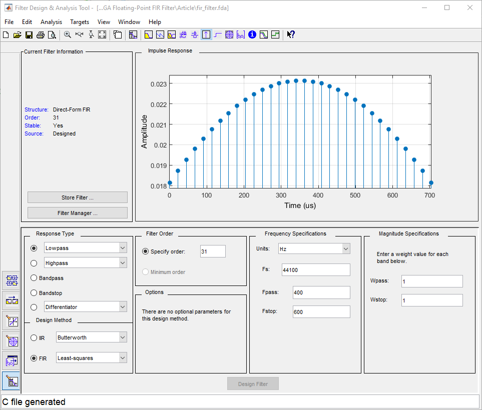
For our example we would like to have a direct-form low-pass FIR filter with a cutoff frequency of about 500 Hz. This will roughly match the characteristics of the IIR filter we implemented in our IIR filter series. We won’t define any attenuation requirements, instead we will indicate the number of taps that we would like to use (which must be equal to or fewer than our DRAM and DROM memories) and see what kind of attenuation we get. We don’t have any requirements regarding the ripple and phase response, so we’ll let those be whatever they turn out to be.
The figure below shows the coefficients generated by Matlab’s Filter Design and Analysis tool. From there we can export the coefficients as a C header file in single-precision floating-point format, which we then must convert to binary or hexadecimal representation and write to the COEF file for the DROM IP core.
FIR Filter Simulation
We are now ready to simulate our FIR filter. We will reuse the testbench from the Equalizer series, but before we do that, we need to instantiate the FIR Filter module inside the Equalizer and add ‘enable’ input signals controlled by the ZedBoard’s switches. This way we will be able to toggle between the IIR and FIR low-pass filters in our Equalizer.
When simulating our FIR filter we need to make sure that the MIF file generated by Vivado after we loaded the COEF file with the filter coefficients is saved in the simulation directory. This is because the simulation file generated in our simulation script for the DROM IP core makes that assumption, and we would have to use a workaround to get the simulation running otherwise.
The figure below shows the result of the FIR filter simulation. The upper analog waveform represents the input snare hit signal, while the lower one represents the output.
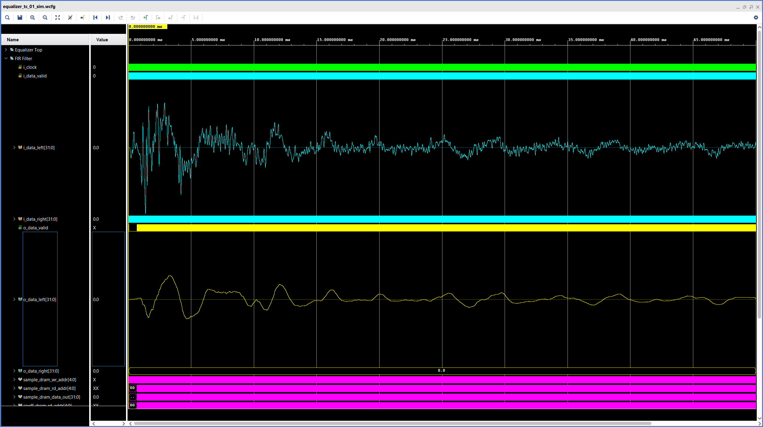
In the waveforms it is clear to see that our FIR filter removes the high-frequency components of the signal, just like we would expect it to. In the second part of this series we will expand our module to support stereo processing and record some audio samples to hear our filter in action.
Cheers,
Isaac
All files for this post are available in the FPGA Audio Processor repository under this tag.